Sign In
 Create Account


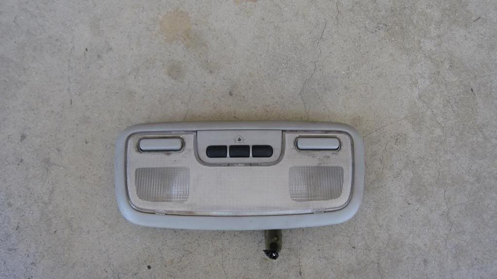
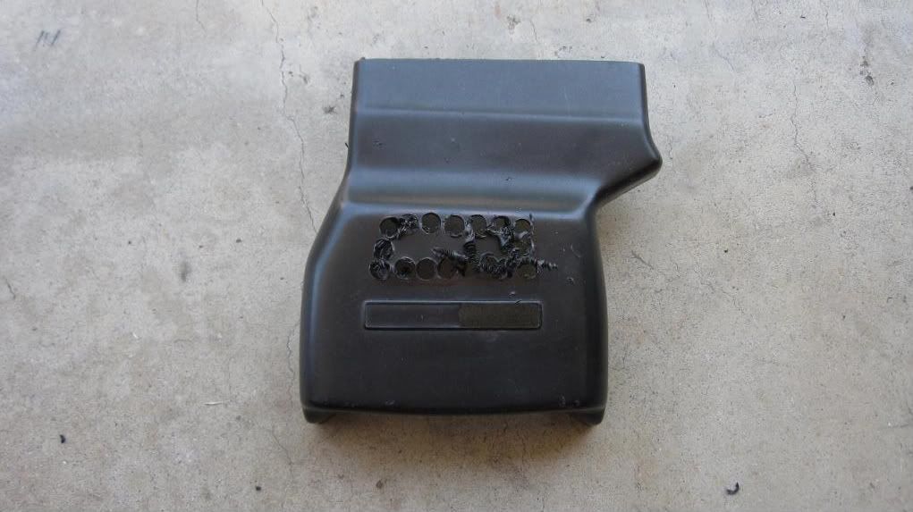
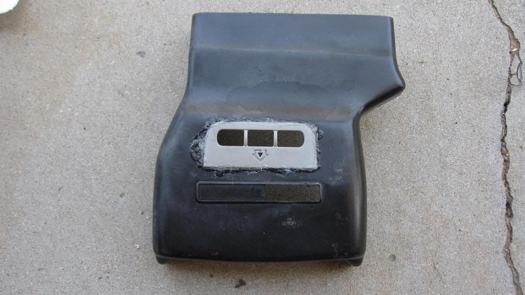
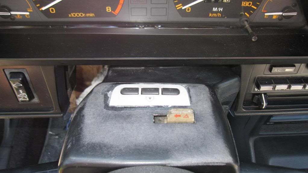
mold it in somewhere. I wanted an easy to replace piece so I decided on the top of the steering column cover
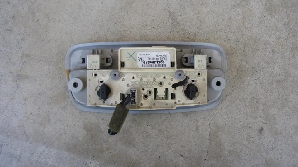
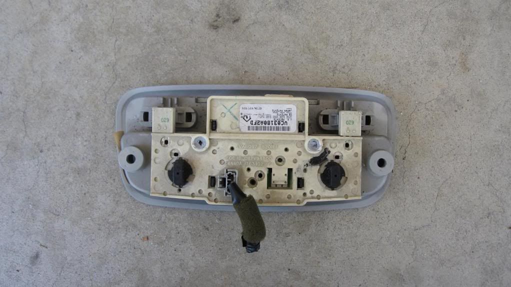
It started out looking like this
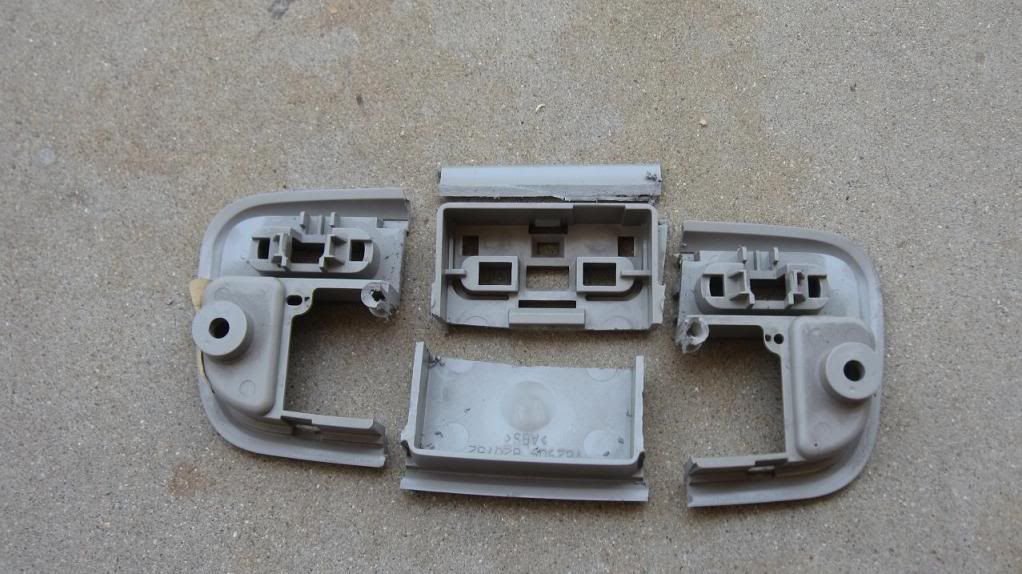
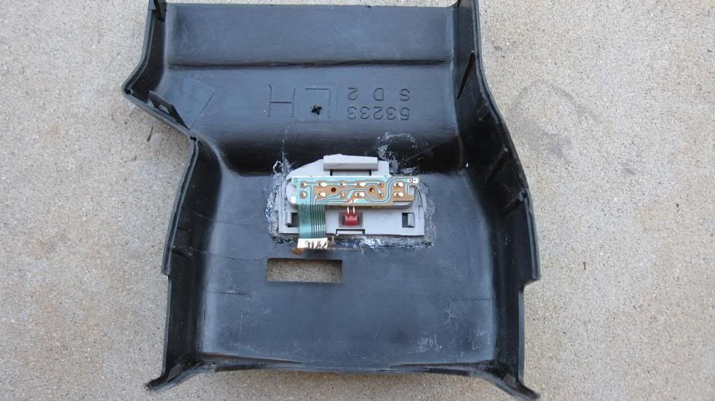
It is held together at two melting spots on the back side. To get apart just grind the melting off
After it is disassembled it will look like this
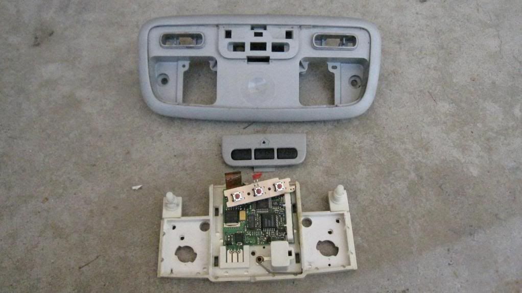
The big square in the middle houses the homelink and needs to cut out.
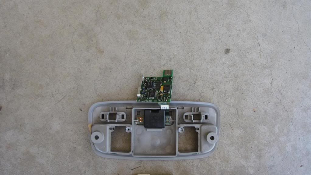
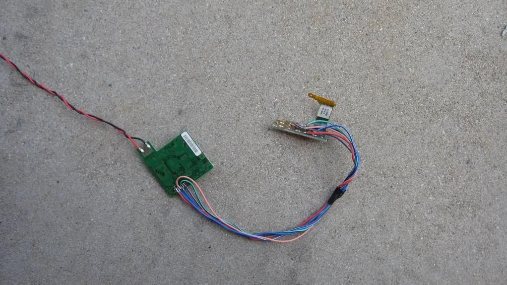
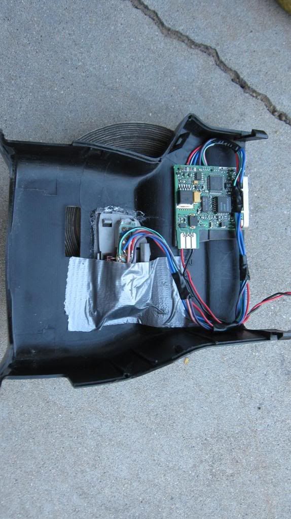
To make it easier and smaller to deal with, the ribbon cable that connects the switches to main board is removed. Wires are soldered to extend the main board so it can be mounted far away
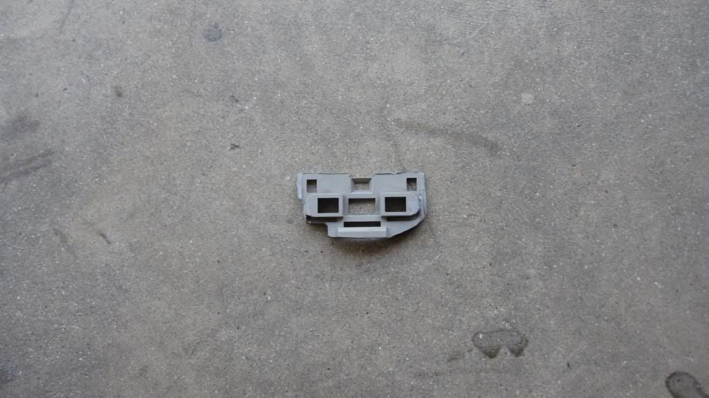
Since the main board will mounted far away the square housing is cut down to bare minimum
The cover needs to be cut out to flush the homelink trim piece. I Drilled out the cover since it quicker than cutting and filed smooth
Set the homelink trim piece in and glue it in

 Back to top
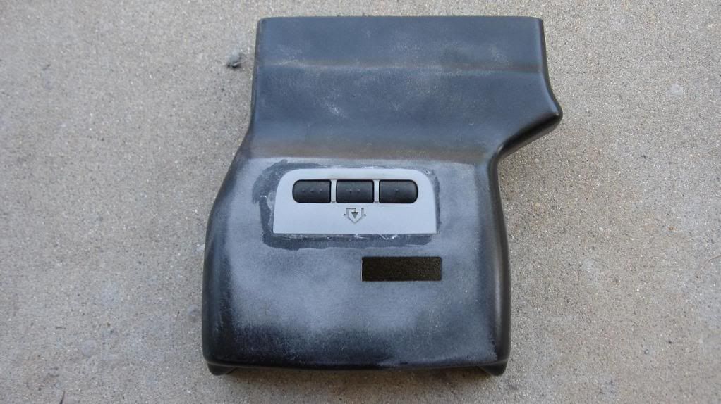
 View Garage