 Sign In
 Create Account
I used the vss stuff from a 2g CRX, per -TJs instructions...
Instrument Cluster Tech - 56k Beware
Started by shadowboy, Mar 12 2004 06:38 PM
64 replies to this topic
#16
 Posted 17 August 2004 - 07:07 AM
-
- Dual Mikunis Rule
-

- Group: 2011 Contributing Member
- Location:Utica, MI
-
Drives: 1987 CRX DX, 2001 Subaru 2.5RS, 2004 Accord EX, 1983 Honda VT500FT
-
Image Gallery
 View Garage

 Back to top
#17
Posted 17 August 2004 - 09:57 AM
-
- RPR Resident Mad Scientist
-
- Group: Members
- Location:Tampa, FL
-
Drives: 87 CRX HF, D16A1-powah
View Garage
QUOTE (civtrx @ Jul 31 2004, 02:01 PM)
was looking over this, and thought i'd see if anyone has the pictures for this thread saved?
-Civ
-Civ
don't worry, the pictures will be back up in a week or so.
Shawn
--------
1987 CRX HF, black top D16A1 power.
Best ET so far: 15.130 @ 88.53mph
--------
1987 CRX HF, black top D16A1 power.
Best ET so far: 15.130 @ 88.53mph
#18
Posted 24 August 2004 - 03:09 PM
-
- corvette contender
-
- Group: Contributing Mod
- Location:Hanover Pennsylvania
-
Drives: your car if i find the keys
-
Image Gallery
i also need some pictures for this. i am making my wiring harness right now. will this work with the 94 integra harness? if someone could help me out with these pictures i would greatly appreciate it.
thanks
Rodney
thanks
Rodney
When I die, i want to go asleep peaceful.......... not screaming and freaking out like everyone else in the car
"i left the bar a little after you and ended up flipping my car in the arbys drive thru"
IM A LOSER!!! my car pulls harder when spinning than any "highly modified" EW

Team BUrnOUt founding member
"i left the bar a little after you and ended up flipping my car in the arbys drive thru"
QUOTE (cbstdscott @ Dec 10 2008, 03:27 PM) <{POST_SNAPBACK}>
Another loser who can not get traction. I feel sorry for him.
IM A LOSER!!! my car pulls harder when spinning than any "highly modified" EW
Team BUrnOUt founding member
#19
Posted 24 August 2004 - 03:48 PM
-

- Leadfoot
-
- Group: Contributing Member
- Location:centreville,vrigina
-
Drives: 1987 crx si 16.6 1/4 mile
-
Image Gallery
View Garage


#20
Posted 27 August 2004 - 10:00 PM
-

- EDM B16A1 INSIDE
-
- Group: 2013 Contributor
- Location:The Netherlands, Europe.
-
Drives: Honda 1G B16 Turbo
-
Image Gallery
View Garage
when will the pics be back up ?
1. EDM 1986 Honda CRX AS - B16A1 engine - OBD1 - Turbo - Stitch welded chassis.
2. EDM 2001 Lexus IS300 3.0 RWD - Daily Drive
#21
Posted 27 August 2004 - 10:07 PM
-

- Super Shuttle
-
- Group: Contributing Mod
- Location:New York State
-
Image Gallery
View Garage
he hosts his pictures from his own server and he is in the middle of a move so have patience. Nice to be needed Shawn? 


#22
Posted 28 August 2004 - 05:15 AM
-
- EDM B16A1 INSIDE
-
- Group: 2013 Contributor
- Location:The Netherlands, Europe.
-
Drives: Honda 1G B16 Turbo
-
Image Gallery
View Garage
thnx for the info nivek2002
1. EDM 1986 Honda CRX AS - B16A1 engine - OBD1 - Turbo - Stitch welded chassis.
2. EDM 2001 Lexus IS300 3.0 RWD - Daily Drive
#23
Guest_-TJ_*
Posted 12 October 2004 - 12:30 PM
Guest_-TJ_*
-

- Group: Guests
EXCELLENT INFO!!!!!!
Waaaay more research (& pictures) than what I figured out back in 2000.
I'll only add that the VSS ground location is CRITICAL. I'm no EE, so I can't answer the "why" question, but if the VSS ground is not connected to the correct screw on the back of the cluster on the tach side, the VSS will not work and you will get a code 17. Just any "ground" will NOT do.
#24
Posted 12 October 2004 - 12:40 PM
-

- push the seat back a little lower watch light bend in the blower
-
- Group: Members
- Location:Stow, OH
-
Drives: '87 Civic Si, '01 Forester
-
Image Gallery
View Garage
i'd also add that swapping parts between Nippon abd Denso gauges isnt easy either.
I tried to swap the VSS from a Nippon teg cluster into a civic Si cluster made by Denso... things don't line up nicely. Ended up finding a Nippon cluster to swap it into instead.
I tried to swap the VSS from a Nippon teg cluster into a civic Si cluster made by Denso... things don't line up nicely. Ended up finding a Nippon cluster to swap it into instead.
#25
Posted 12 October 2004 - 12:43 PM
-

- In the left lane
-
- Group: Members
- Location:NoVA
-
Drives: '82 Toyota Cressida: Fond Memories, '85 Civic 1300 w/ '88 Integra Mechanicals
Mine worked just fine running to the gnd on the steering column. I'm an EE, and for these systems, any ground should do. Are you sure that you had a good connection and used good wire?
#26
Posted 12 October 2004 - 05:12 PM
-
- RPR Resident Mad Scientist
-
- Group: Members
- Location:Tampa, FL
-
Drives: 87 CRX HF, D16A1-powah
View Garage
QUOTE (rally25rs @ Oct 12 2004, 01:40 PM)
i'd also add that swapping parts between Nippon abd Denso gauges isnt easy either.
I tried to swap the VSS from a Nippon teg cluster into a civic Si cluster made by Denso... things don't line up nicely. Ended up finding a Nippon cluster to swap it into instead.
I tried to swap the VSS from a Nippon teg cluster into a civic Si cluster made by Denso... things don't line up nicely. Ended up finding a Nippon cluster to swap it into instead.
you are indeed correct, sir.
i lucked out, my 87 HF i own and the 89 teg LS i used to own (which was a MAJOR parts donor for this project), both had nippon clusters, which is what this writeup is based on.
Shawn
--------
1987 CRX HF, black top D16A1 power.
Best ET so far: 15.130 @ 88.53mph
--------
1987 CRX HF, black top D16A1 power.
Best ET so far: 15.130 @ 88.53mph
#27
Guest_-TJ_*
Posted 13 October 2004 - 03:45 PM
Guest_-TJ_*
-
- Group: Guests
I had mine grounded to the steering column and it did not work (from the ECU's perspective).
When I relocated the same wire to the correct screw on the back of the cluster, *magic*, it worked.

When I relocated the same wire to the correct screw on the back of the cluster, *magic*, it worked.
#28
Posted 13 October 2004 - 10:03 PM
-

- Slowpoke
-
- Group: Members
- Location:Hawaii
-
Drives: 1985 honda crx si
View Garage
Adding to the VSS knowledgebase:
first some info on my car:

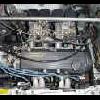
now a pic of my 85 crx si speedo:

and a pic of an 86-87 integra speedo:

as you can see, the teg has a larger metal thing and is thus closer to the magnetic switch of the pulser. the crx is smaller in diameter and fails to "reach" the pulser.
all this time i've been super f'in busy. finally got to run further tests. according to the gen 2 crx manual, spin the speedo and the multimeter will allow some continuity between the two terminals of the pulser (pulses).
I put an 89 crx pulser on the 85 speedo, no pulses generated.
i put the same pulser on the 87 teg speedo, pulses generated EQUAL to pulses generated when same pulser was on 89 crx speed unit it came from.
upon further exam, i discovered the above pictures and statement.
yet to run tests. will post back when i can with results, but i'm 99% sure problem solved. I HOPE. thanks to all for spending you precious life's time to contribute to the vss troubles.
summary:
85 crx si will need to have the speedo unit switched to a 1g HF, 1g or 2g teg, 2g crx that have the speed pulser.
the gauge face will fit fine, all unscrew and screw. *be careful with removing of the needle*
reuse the 85 crx si trip meter, fit fine.
i am not using the amplifier as the honda schematic's do not require it. i hope it works: crosses fingers
first some info on my car:
now a pic of my 85 crx si speedo:
and a pic of an 86-87 integra speedo:
as you can see, the teg has a larger metal thing and is thus closer to the magnetic switch of the pulser. the crx is smaller in diameter and fails to "reach" the pulser.
all this time i've been super f'in busy. finally got to run further tests. according to the gen 2 crx manual, spin the speedo and the multimeter will allow some continuity between the two terminals of the pulser (pulses).
I put an 89 crx pulser on the 85 speedo, no pulses generated.
i put the same pulser on the 87 teg speedo, pulses generated EQUAL to pulses generated when same pulser was on 89 crx speed unit it came from.
upon further exam, i discovered the above pictures and statement.
yet to run tests. will post back when i can with results, but i'm 99% sure problem solved. I HOPE. thanks to all for spending you precious life's time to contribute to the vss troubles.
summary:
85 crx si will need to have the speedo unit switched to a 1g HF, 1g or 2g teg, 2g crx that have the speed pulser.
the gauge face will fit fine, all unscrew and screw. *be careful with removing of the needle*
reuse the 85 crx si trip meter, fit fine.
i am not using the amplifier as the honda schematic's do not require it. i hope it works: crosses fingers


#29
Posted 14 October 2004 - 12:01 AM
-
- RPR Resident Mad Scientist
-
- Group: Members
- Location:Tampa, FL
-
Drives: 87 CRX HF, D16A1-powah
View Garage
was your Si and teg/2g CRX clusters of the same brand?
the size difference of the "drum" could be attributed to that, or it could just be because of the g1 Si's lack of a true VSS.
the cluster i used at the start of this thread was from a nippon-seiko g1 CRX HF. the teg cluster was a nippon-seiko 89 teg LS cluster.
the size difference of the "drum" could be attributed to that, or it could just be because of the g1 Si's lack of a true VSS.
the cluster i used at the start of this thread was from a nippon-seiko g1 CRX HF. the teg cluster was a nippon-seiko 89 teg LS cluster.
Shawn
--------
1987 CRX HF, black top D16A1 power.
Best ET so far: 15.130 @ 88.53mph
--------
1987 CRX HF, black top D16A1 power.
Best ET so far: 15.130 @ 88.53mph
#30
Posted 14 October 2004 - 09:19 AM
-
- In the left lane
-
- Group: Members
- Location:NoVA
-
Drives: '82 Toyota Cressida: Fond Memories, '85 Civic 1300 w/ '88 Integra Mechanicals
When I added my vss, I had a similar issue with my civic's speedo being unable to manipulate the pulser. This forced me to swap over both the speedo AND the odo (regular and trip). One caveat you forgot to note, at least in my case, is the stop for the speedo needle. The integra had a stop on the speedo face to keep the needle from going past zero, while the civic had an internal stop. By placing the integra speedo on the civic face, you no longer have a stop to keep the needle at zero. It's not a huge deal, but it makes getting the needle initialized at '0' before install important.
On a related note, there is no such thing as a VSS amplifier. The VSS is passive, meaning there is no electronic trickery powering it. I'm well aware of the circuit board it attaches to. However, if you follow the circuit path on the board from where the two wires from the vss connect, trace it to the 5-pin connector, and you will see a direct path. No transistors or ICs in the path anywhere, and all the wiring diagrams in the service manuals back it up. That is because the ecu reads the pulses as either short to ground (0 V) or open (5 V). The vss is shorted (0 V) in its initial state, and then opens four (4) times for every revolution of the speedo cable. This is why it is possible to run a wire from the ecu directly to the vss and run the vss to ground on the other connection, and get it to work. It was doing that anyway.
The above findings are based on my vehicle setup and my research. Hopefully, this clears up some issues that folks have had with the vss that are similar to the situation I was in.


Community Forum Software by IP.Board
Licensed to: Red Pepper Racing