Jump to content


H22 Crx Project


  • You cannot reply to this topic
230 replies to this topic

#46
strudel

  • Leadfoot
  • PipPipPipPipPip
    • Group: 2011 Contributing Member
    • Location:Edmonton, AB
    • Drives: 2009 AUDI TT 3.2L, Project Teg powered Austin Mini Van
    • Image Gallery
David,

Too late for you to look at this option but found this comment on another board as to the size and constraints of the H22. There was no elaboration as to which series/year Civic. JS

QUOTE
There are some civic owners running the H22 with a B- series gearbox with an adapter plate might make it easier (but not cheaper!)

If you want one of these Logos send me a PM

aan.jpg


Austin Mini Van with DOHC Honda HP
http://www.angelfire.com/droid/strudel
Honda reliability and power combined with Mini cachet and style.


#47
firstgencrx

  • This thing should fit!
  • PipPipPipPipPip
    • Group: 2013 Contributor
    • Location:opɐɹoloƆ 'suılloƆ ʇɹoℲ
QUOTE (strudel @ Jan 26 2010, 11:24 AM) <{POST_SNAPBACK}>
David,

Too late for you to look at this option but found this comment on another board as to the size and constraints of the H22. There was no elaboration as to which series/year Civic. JS


It's an H to B adapter. I've seen it even here on RPR. It lets you use a shorter transmission with the H motor. If someone was going to use an H in a 1G, that would make it easier for sure. Then all you would need is only two special engine mounts made, I think. The trans mount and axles would be used from a B series swap. Correct me if I'm wrong.

David
Sharing with others what I do for myself!

My H22 CRX Project

Posted Image

#48
strudel

  • Leadfoot
  • PipPipPipPipPip
    • Group: 2011 Contributing Member
    • Location:Edmonton, AB
    • Drives: 2009 AUDI TT 3.2L, Project Teg powered Austin Mini Van
    • Image Gallery
Other than the adapter plate that matches tranny to block what has to be done on the inside so that everything mates up? Splines, shaft length, clutch etc? In case I ever want to mate a non matched set in the other project.

Just thought of this and correct me if I am wrong. The tranny would stay in the oem position with axles. The engine would shift towards the timing side the thickness of the adapter plate and the engine mounts would have to be altered to correct the movement change. As to the inside I thought this out a bit after I asked. Just needs another spacer on the flywheel crank connection the thickness of the tranny/block adapter plate. Simple actually. JS

Edited by strudel, 26 January 2010 - 08:02 PM.

If you want one of these Logos send me a PM

aan.jpg


Austin Mini Van with DOHC Honda HP
http://www.angelfire.com/droid/strudel
Honda reliability and power combined with Mini cachet and style.


#49
EuphoricBlue

  • Leadfoot
  • PipPipPipPipPip
    • Group: 2011 Contributing Member
QUOTE (strudel @ Jan 26 2010, 04:33 PM) <{POST_SNAPBACK}>
Just thought of this and correct me if I am wrong. The tranny would stay in the oem position with axles. The engine would shift towards the timing side the thickness of the adapter plate and the engine mounts would have to be altered to correct the movement change.


Can't alter something that doesn't exist smile.gif

Don't forget that you are making custom mounts anyway, just compensate for the shift in the design stage.

#50
strudel

  • Leadfoot
  • PipPipPipPipPip
    • Group: 2011 Contributing Member
    • Location:Edmonton, AB
    • Drives: 2009 AUDI TT 3.2L, Project Teg powered Austin Mini Van
    • Image Gallery
QUOTE (EuphoricBlue @ Jan 27 2010, 04:24 PM) <{POST_SNAPBACK}>
Can't alter something that doesn't exist smile.gif

Don't forget that you are making custom mounts anyway, just compensate for the shift in the design stage.

I get the second part of your comment but over my head on the first. I was just wanting to find out how an adapter plate would work, on any type of engine/tranny combo, and what other consequences are involved. I know someone that wants to do a rotary FWD conversion and that's exactly what would need to be done. The other major concern would be the mount for the half shaft location. On a B series it would need to slide the difference in distance and some interesting fab work there on the half shaft bracket. Doubt you could just elongate the holes. I guess it's more fun if the project is more difficult. laugh.gif JS

If you want one of these Logos send me a PM

aan.jpg


Austin Mini Van with DOHC Honda HP
http://www.angelfire.com/droid/strudel
Honda reliability and power combined with Mini cachet and style.


#51
EuphoricBlue

  • Leadfoot
  • PipPipPipPipPip
    • Group: 2011 Contributing Member
Strudel, the first bit was a direct reply to this line, "The engine would shift towards the timing side the thickness of the adapter plate and the engine mounts would have to be altered to correct the movement change."

I was assuming you were talking about this configuration of engine and car so I was just saying that there are no existing mounts to alter, you have to fab everything anyway so the difference can be made up in the design process.

#52
firstgencrx

  • This thing should fit!
  • PipPipPipPipPip
    • Group: 2013 Contributor
    • Location:opɐɹoloƆ 'suılloƆ ʇɹoℲ
Hello all.

I know that I already posted most of this in another location on the forum. I've decided to update this installation thread, and move some of that stuff into my build thread. With all the installation guides in one place, it will be much easier to find all of them down the road. Of course, there is a growing and helpful table of contents in the very first post in this build thread. wink.gif So onto the installation instructions for some of the kit I've created over the years.

Rear Trailing Arm Spherical Bearing Installation: Part One

The next two posts will be the installations instruction for the rear trailing arm spherical bearing kits I developed. I made some subtle changes to the parts that I exposed everyone to in the "Holy Sphericals Batman" post. Nothing big, just some improvements to the design.

Here are all of the parts that come in the kit:


When you get the kit form me, I will have already pressed the spherical bearings into the housings, and installed the snap rings:


Important Note!

Because the chassis mounting bolt on my car is 10mm, I made the dumb assumption that all the other 1G/3G's out there where the same. NOT! So for the very few folks that have these kits, if your car has the 12mm bolt, don't worry. If you are not able to drill out the inner sleeve, or find someone who can do it for you, I will gladly whip up a set of 12mm sleeves for you. cool.gif


One of the changes I made is I tapered the back of the housing to clear the center bushings. Helps make sure everything articulates with full range of motion:


It is assumed that you have removed the old OEM rubber bushing from the trailing arms. If you need to find out how to do this, there is a great write-up in the kakabox build project pages.

Use a little 2" diameter wire wheel to clean out the big bushing hole on the trailing arms. Make that hole nice and clean. You need bare steel showing:


Once everything is cleaned up, we need to make a clearance hole for the grease fitting. Do this by scribing a line 1/2" from the flanged face of the bushing hole:


Choose a location so that the grease fitting points downward. Of course, you can put it anywhere you want, but downward will be the easiest location to get to it. Center punch a mark on the line, and drill a 5/16" to 3/8" clearance hole. It is super important that you get the center of this hole 1/2" from that flanged face. So if you need to center drill and use a smaller bit first, do it.

You need to decide if you're going to bolt your spherical bearing housings in, or weld them in. I have chosen to tack weld them in, so I have drilled three small holes around the perimeter of the trailing arm bushing hole close to the flange. If you choose to bolt them in, wait until the bushings are installed. Then just pick a couple of spots to drill and tap for some small 10-32 bolts. Personally, I think tack welding them in is the better and faster option. If you choose to tack weld the housing into the arm, drill three 1/4" holes around the end of the arm near the flange. It will be those holes you fill when you tack weld the housing in.

Once the grease fitting clearance hole and weld holes are drilled, it's time to press the spherical bearing housing into the trailing arm. The housing will be pressed in from the flanged side. It's important to line up the grease fitting clearance hole with the grease fitting hole in the housing:


To press in the housing, use either a large bench vise:


Or a shop press. Just be careful to line things up and make sure you don't start off crooked:


Press the housing until it is flush with the flanged end of the trailing arm bushing hole:


And make sure the grease fitting hole is lined up:


At this point, go ahead and install the grease fitting. Another change I made to this design is that the grease fitting now threads into the spherical bearing housing, and not the rear trailing arm. This will direct the grease more to the bearing instead of leak from the perimeter. Be careful and don't tighten the fitting too tight. Believe me when I say, those little fittings snap off real easy, so don't go crazy with the wrench. I typically use a nut driver to install them. That keeps me from getting them too tight.


Continued in next post:
Sharing with others what I do for myself!

My H22 CRX Project

Posted Image

#53
firstgencrx

  • This thing should fit!
  • PipPipPipPipPip
    • Group: 2013 Contributor
    • Location:opɐɹoloƆ 'suılloƆ ʇɹoℲ
Rear Trailing Arm Spherical Bearing Installation: Part Two

It's now time to tack weld these housings in. I just filled the three perimeter holes I drilled near the flanges. They look something like this:


Use a wet wag to keep the heat form spreading to the bearing. The bearing has some rubber seals that need to stay cool, otherwise you might melt them. It's easier than it looks to keep this part cool while you're tack welding.

If you are not comfortable filling small holes, you can put three short stitch welds on the flange face. They only need to be 1/2" to 3/4" long to do the job. It looks something like this:


Either way you decide to do it, you don't need much. That housing presses into the trailing arm bushing hole pretty tight. The tack welds, or retaining bolts are only for insurance.

One more thing you might consider doing just for safety. I noticed that the arm is only pressed around the factory sleeve. You might put a few short welds around the edge to insure it never comes loose. This is how I did mine, and what I mean:


It doesn't take much to keep that OEM arm from ever moving.

The final step is to install the chassis bolt bushings. The long bushing goes in first from the tapered deep end of the housing:


Then the sleeve goes on next, with the large chamfer toward the spherical bearing:


Again, if you find that your car uses the 12mm chassis mounting bolts, and you are not able to drill the original 10mm hole out, just let me know and I will get you some 12mm inner sleeves. But please try, I don't want to make these unless I have to. wink.gif

The trailing arm with it's new spherical bearings should bolt right into the chassis end mount:


When you are finished and satisfied with your work, take a grease gun to those zerks and give them a good squirt. Grease them till you see the stuff coming out from the edges.

It would also be a good idea to put some good primer and paint on your new modified arms before final installation. We fight rust enough already!

Take care all,

David
Sharing with others what I do for myself!

My H22 CRX Project

Posted Image

#54
firstgencrx

  • This thing should fit!
  • PipPipPipPipPip
    • Group: 2013 Contributor
    • Location:opɐɹoloƆ 'suılloƆ ʇɹoℲ
Torsion Bar Spherical Bearing Kit Installation Guide: Part One

The installation is straight forward enough. The hard part is getting the old rubber bushings out. You can find my write-up of how to get the old bushings out here:
http://www.redpepper...showtopic=46131

Get past that step, and you are truly home free! laugh.gif

I will be re-using some of the pictures from the "Holy Sphericals Batman" thread.

The torsion bar spherical bearing kit comes with all the bits in this photo:


When you get the kit, the big spherical bearings will be already pressed into the housings and snap rings installed for you:


The kit also comes with a little tool that helps you press the housing into the sub-frame. You will need to supply a 16" long piece of 3/4" all-thread, and a couple nuts and washers to complete the installation tool. You can get the nuts and all thread at any hardware store:


After the old bushings have been removed and everything cleaned up, the first step to installing these bearings is to press the torsion bar arms into the spherical bearing. But first, put some grease around the front of the spherical bearing where the extra O-Rings go:


Then onto the special spacer washer. Place the stepped side of the washer toward the O-Ring:


When pressing the arms into the spherical bearings, it's important to back up the press fit on the inner ball of the spherical bearing, NOT on the housing. I would suggest you simply use the flat drive end of a large socket. Make sure the socket is larger in diameter than the flats on the inner ball:


You can either use a large bench vise:


Or a shop press. Be careful to start out things nice and straight before you start to press these arms in. If things get crooked, you will destroy the arms:


Once the torsion bar arm is pressed into the spherical bearing pack, it's time to prepare the torsion bar tube on the front sub-frame. Use a pair of calipers to scribe two lines parallel to the front face of the torsion bar tube. One line will be 0.575" from the front face, the second will be 1.18" from the front face:


Use a square to scribe across parallel to the torsion bar. Make sure you put your cross marks far enough on the side of the tube so the grease fitting does not protrude below the scrub plane (like I did the first time! D'oh!):


Continued in next post:
Sharing with others what I do for myself!

My H22 CRX Project

Posted Image

#55
firstgencrx

  • This thing should fit!
  • PipPipPipPipPip
    • Group: 2013 Contributor
    • Location:opɐɹoloƆ 'suılloƆ ʇɹoℲ
Torsion Bar Spherical Bearing Kit Installation Guide: Part Two

Center punch your newly scribed cross hairs:


Now drill the rear hole 1/4" for the retaining bolt. Drill and tap the front hole 1/4-28 for the grease fitting. If you need to center drill the the punch marks first to help keep the drill bit from wandering, do it:


Here is a shot of the same side, but after I filled the holes I put too close to the bottom, and re-drilled them more to the side. Easy enough to fix:


Much better. laugh.gif


Now you are ready to press in the assembly into the torsion bar tube using the special tool I sent you with your kit. Take your 3/4" all thread that you bought, and slide it down the torsion bar tube.


Place one large washer and nut at the rear end of the torsion bar tube:


Place the spherical bearing assembly onto the front end of the torsion bar tube, and put the special tool over the threaded rod:


Put a nut and washer on the end (I know, I forgot to put the washer on in this photo dry.gif ):


At this point, it's a little of a juggling act. Before you start to tighten the 3/4" nut to press the assembly into the torsion bar tube, you need to do two things:

1. Make sure the nut at the rear of the tube is as centered as possible in the tube (you don't need to be perfect, just close)

2. Make super sure that the holes you drilled in the side of the torsion bar tube line up with the holes in the bearing assembly. You need all of those holes to line up when the bearing assembly is fully pressed in:


It should look something like this when pressed in:


The spherical bearing assembly will press into the sub-frame until it is flush with the front of the torsion bar tube.


Finish off the installation by installing the grease fitting, and the retaining bolt:


Here is what it looks like on the other side with the holes down lower:


You can use a little lock tight on the retaining bolt if you like. Use some carb cleaner on the threads of the bolt and the threads in the hole before putting the lock tight on the bolt. You can also grease the bearing pack now if you like.

Tomorrow, I will show how to align the front sub-frame under the chassis, and install the radius arm spherical bearing kit.

Take care all,

David
Sharing with others what I do for myself!

My H22 CRX Project

Posted Image

#56
firstgencrx

  • This thing should fit!
  • PipPipPipPipPip
    • Group: 2013 Contributor
    • Location:opɐɹoloƆ 'suılloƆ ʇɹoℲ
Radius Arms Spherical Bearing Installation: Part One

I almost got the radius arms spherical bearings installed tonight, but I ran out of time. So I will show you what I have so far. cool.gif

What comes in the radius arms kit:


Sorry if these instruction seem a little too detailed. I don't want to make anyone think "I'm Dumbing It Down." These are not as easy to install as they look, so I want to be as detailed as possible. This will only make it simpler for you. I had some trouble getting these in the first time, and as a result, I've discovered the easiest way to do this.

These have to be installed with the sub-frame removed from the car, so take it out, and clamp it into a sturdy vice on your workbench. Just like you did when you installed the torsion bar arm spherical bearings. wink.gif

The first thing we need to do is open up the smallest diameter opening/step in the sub-frame. This is where the old rubber/poly bushings where. I'm talking about this:


We need to open up that inside diameter of that step to something between 1.230" and 1.250". The reason is so down the road, you will be able to replace the spherical bearing with the housing installed in the sub-frame. I don't have a measuring tool that will easily reach down inside to measure the opening, but I do have sockets laying around and a pair of calipers. The stock ID is about 1.180", and we need an opening that is more than 1.200".

The best tool to do this is an air die grinder and a carbide bit. If you don't have an air grinder, you can just use an electric drill. I had an old beat-up bit lying around that will be perfect for the job:


Mount it in a die grinder or drill, and you're ready!


Be careful and systematic. You are not taking much material out of there, so don't go crazy. I was able to work around the ID, and increase the opening to 1.230". Be careful to remove equal amounts all around. You don't want to change the center of the hole:


As you can see above, very little material was removed to open it up. I also didn't change its shape much either.

To gage my progress, I just used a socket I had in my box, that just so happened to measure 1.230" in diameter. Once the socket fit in the hole, I knew I was there:


I also changed out to a sanding roll to smooth off my grinding and remove some of the burr left behind by the carbide cutter:


But even after sanding, a small burr was still left:


So I took a de-burring tool to the edge. This is something all of you should have in your box if you don't already:


What you need to do next is feel with your finger tips, the tops of the factory spot welds inside the sup-frame housing:


Some of these spot welds stand proud, and they need to be brought down flush with the inside diameter of the opening. Use the die grinder and a bit or sanding roll to smooth these high spots off. The reason for this is simple. The spherical bearing housing you are going to install later is a small press fit, and I don't want anything dragging on the sides of it while it's being pressed into the sub-frame.

Continued in next post.....
Sharing with others what I do for myself!

My H22 CRX Project

Posted Image

#57
firstgencrx

  • This thing should fit!
  • PipPipPipPipPip
    • Group: 2013 Contributor
    • Location:opɐɹoloƆ 'suılloƆ ʇɹoℲ
Radius Arms Spherical Bearing Installation: Part Two

I think the best way to hold the spherical bearing housing in the sub-frame is to tack weld it in. So I'm going to be drilling a few small 1/4" diameter holes around the perimeter of the sub-frame bushing housing.

These next few steps are very important.

The spherical bearing housing is pressed into the sub-frame, such that the inside end of the housing registers against that opening we ground on a bit in the first part of this installation guide. In other words, we press the spherical bearing housing into the sub-frame, tight up against that smaller inside diameter step. Why is this important? It is the distance from that step that will tell you where to drill your holes.

On my sub-frame, I calculated that the correct fore and aft elevation for the location of the grease fitting was 0.400" from the front face of the sub-frame bushing housing. Like this:


This dimension was taken by carefully measuring from the inside of the step, outward to the face of the sub-frame opening. Then I just subtracted the distance I needed for the location of the grease fitting. It's important for you to know that because these sub-frames are spot welded together, and are obviously not precision items. Your sub-frame may be a little different than mine. You may need 0.500" from that same face, or less. So you will need to calculate this location carefully.

Once I found my location, I scribed a line like shown above, and center punched it like below:


This first location is for the grease fitting only, and is rotated such that it is as close to the sub-frame mounting flange as practical.

After I got the grease fitting location figured out, I then made four more marks where the tack welds will go that retain the spherical bearing housing. I use the same elevation dimension I used for the grease fitting. After center punching them as well, I started to drill holes. At first, I drill all holes 1/4". I put two holes on the top half of the sub-frame, and two below:


Once the holes are drilled, I de-burr and clean them up:


Make sure you de-burr the insides of the holes too:


Now, the hole for the grease fitting is too small at 1/4", so I open that one hole up to 3/8":


And to make doubly sure there is no problem with my elevation calculation, I take a rat-tail file and slot that grease fitting hole. The hole does nothing but make clearance for the fitting, so don't worry about making it bigger:


I carefully elongate the whole for insurance. Something like this would be good:


Like I said above, the elongation is just for insurance. If you should have gotten that hole location wrong, it's a bitch to get the spherical bearing housing out of the sub-frame after it's pressed in. I found that out the hard way. tongue.gif

Once you have slotted the grease fitting hole, de-burr both the inside and outside of the new slot.

Continued in next post....
Sharing with others what I do for myself!

My H22 CRX Project

Posted Image

#58
firstgencrx

  • This thing should fit!
  • PipPipPipPipPip
    • Group: 2013 Contributor
    • Location:opɐɹoloƆ 'suılloƆ ʇɹoℲ
Radius Arms Spherical Bearing Installation: Part Three

Now it's time to press the spherical bearing housing into the front half of the sub-frame. The spherical bearing housing come with the bearing and inner sleeve pressed in already for you. You don't need to remove the bearing or sleeve to finish this installation:


When I designed this spherical bearing housing, I used the absolute largest bearing I could without gutting the inside of the sub-frame bushing hole. This made the housing a little too large and long for an easy fit. To put this spherical bearing housing into the sub-frame, you need to work it in by tilting it first:


The spherical bearing housing is a press fit into the sub-frame, so place it with the grease fitting aligned with the slot you made earlier:


Now we need to devise a simple way to press this into the sub-frame. I used some large 1/2" drive sockets, and a length of 1/2" all thread. For the front, use a socket that is smaller than the OD of the spherical bearing housing, but not too small. The face of the housing wants to fit the diameter of the socket:


Alternately, you could use a short piece of tubing or anything really that has the correct diameter, and a large enough hole in the middle to clear the spherical bearing inner sleeve. I ended up using a piece of round aluminum with a large hole in the middle.

Use a large socket for the back end of the sub-frame as well:


A length of 1/2" all-thread, a couple nuts and washers, and you end up with something like this:


VERY IMPORTANT! Make sure before you start to press this spherical bearing housing into the sub-frame, that your grease fitting hole in the housing lines up with the slot you made in the sub-frame. When you think you are lined up and ready, only tighten the rear nut, and hold the front nut steady. I found this out the hard way. In my first go at this, I tightened the front nut, and the spherical bearing housing turned a little. Opps!

So tighten only the rear nut, and hold the front one still:


As you slowly draw the spherical bearing housing into the sub-frame, check to make sure the grease fitting hole is lined up with your slot. Stop along the way and check:


If everything looks good, press that spherical bearing housing all the way into the sub-frame. That inner smaller diameter step inside is what it will stop against:


Perfect! cool.gif

You can see here how the spherical bearing housing is now pressed up tight against that inside step we opened up earlier:


Well, these last three posts took more than two hours to do, so I'm going to finish this installation tomorrow. rolleyes.gif

Take care all!

David
Sharing with others what I do for myself!

My H22 CRX Project

Posted Image

#59
kakabox

  • Turd Polisher
  • PipPipPipPipPip
    • Group: 2012 Contributor
    • Location:Seattle, WA 98115
    • Drives: from point 'A' to point 'B' daily.
    • Image Gallery
    Garage View Garage
QUOTE (firstgencrx @ Feb 26 2010, 09:28 PM) <{POST_SNAPBACK}>
Well, these last three posts took more than two hours to do... rolleyes.gif

Trust me, I know that goes!

Very good David, I can't wait to get started on my install.

#60
firstgencrx

  • This thing should fit!
  • PipPipPipPipPip
    • Group: 2013 Contributor
    • Location:opɐɹoloƆ 'suılloƆ ʇɹoℲ
Radius Arms Spherical Bearing Installation: Part Four

Now that the spherical bearing housing is installed, go ahead and put the grease fittings in. Tighten them down with a nut driver if you've got one. Do not over tighten these fittings. They snap off real easy. I know:


The grease fitting could be another 1/16" longer to fit better, but you'll get them tight if your careful. The next longer fittings are way too long, so these are the ones I needed to go with. They look good and fit nice when they are in there, and the grease gun fits over them:


It's now time to tack weld the spherical bearing housings into the sub-frame. Put the all-thread press assembly back on to one side. I want you to put some pressure on the spherical bearing housing when we tack weld. This insures it's in there tight.


Now, this is tricky, so be careful, and go slow. No need to rush through this part of the installation. The housing on this spherical kit is thick enough, that there is a fair amount of mass around the bearing:


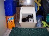
And there is a lot of mass in the sub-frame:


This is important, because this mass will draw heat away from where you are welding. We don't want to over heat the spherical bearing housing. This will melt the little rubber seals, or worse, temper the bearing.

It is easier than you might think. The trick here is to not spend much time welding, and a lot of time cooling. You can use a wet rag, or just compressed air like I did, what ever is convenient for you. I don't allow myself to weld longer than two seconds, then I cool, cool, cool. I use my hand to tell me when things are cool enough to weld again. If you use water, you will need to use compressed air to clean out the water before you start to weld again. Otherwise, the water will boil when you weld, and cause porosity or foaming in the weld.

This is how I did it using the TIG. I first extend the tungsten a bit from the cup, I turned up the argon level to 20 cubic feet per hour, and I fused the bottom of the hole. What I mean by that is, I created a small molten puddle between the spherical bearing housing, and the side of the hole in the sub-frame, flowing them together.

This is a bad shot, but what it shows is how I fused one side of the hole in the sub-frame to the spherical bearing housing at the bottom of the hole:


Do this to at least two side of the hole, cooling between steps.

Next, I drop my rod into the hole, and allow a puddle to form on the spherical bearing housing, and fill with rod till it melts onto the side of the hole. At this point, the hole should be more than half full of filler material. I do this very fast. Less than two seconds. Cool between steps. Use your hand to make sure everything is good.

Once I'm convinced the housing has some filler material melted to it and the side of the wall of the sub-frame, I go ahead and fill the hole. Here are the two bottom holes filled:


This doesn't need to be fancy, and you don't need to perfectly fill the hole. If there is an air void under the top of your weld, that is OK. As long as you get filler material melted between the spherical bearing housing and the sub-frame, you are good. It dosn't take a lot to hold this housing in the sub-frame, so try to suppress the urge to really go at this and melt everything together. If you hire someone to weld this in, make sure he/she reads this. This is not a critical high strength job. Four tack welds will be super strong holding this spherical bearing housing from ever moving forward. Remember, that step/flange at the back of the housing is doing all of the work keeping the housing from ever moving rearward. It's in the rearward direction that the high forces are present. So no need to go crazy here sticking these in there.

Here are the top two holes finished:


You can see from this picture, that I had very little discoloration from the welding. It's hard to see, but what I have is a bit of brown soot formed from the oils burning off the surface of the spherical bearing housing. Most of it wiped off with a rag. If you can't see it, the brown stain is on the right side of the housing:


What I have done here has not damaged the bearing inside the housing.

If you use a mig, my advice is to slow down the wire a bit, and turn up the heat a little. Mig's weld very cold at first, or what they call "Cold Start." They don't really start to make heat and melt stuff together until they get going a bit. So by slowing down the wire, and turning up the heat, we are insuring that the filler wire melts to the spherical bearing housing first, then the side of the wall of the drilled hole. Practice on some junk first, and convince yourself you are sticking the two pieces together. Just take a piece of material similar in thickness to the two layers of the sub-frame bushing opening, and drill a 1/4" hole in it. Then lay a second piece of material under the hole. Practice reaching down into the hole with your mig filler wire, and tacking the two parts together.

Same rule with the mig, two seconds weld, cool, cool, cool. Once you get it set up right, the mig is probably the better machine for this job. I chose to use the TIG simply because I'm more comfortable with it. I can see directly what I'm doing, and if I got it. But if set up and adjusted with some test pieces first, the mig is the better and faster way to do this job.

Again, if you hire someone else to mig these in there, don't let them go crazy with too much heat.

Continued in next post:
Sharing with others what I do for myself!

My H22 CRX Project

Posted Image