OK, I think I have not been very clear in explaining what is happening with this system, so I'm going to try and explain this as best I can.

I just wish you guys where standing next to me with the car on it's back, and I know you would understand in a second what's up.

I've been a little miss-leading with my explanations, simply because I was trying to keep things as simple as I could. In the spirit of keeping things clearer, I'm going to call the arm with the integral ball joint the radius arm (that's what Honda calls it, Thanks Kaka!), and the remaining arm in this system the torsion bar arm, or tbar arm for short.
First, the dominant axis of rotation in this system is the torsion bar axis. The reason for this is simple. The bushing out on the end of the torsion bar is 10 times more stiff, or non-flexible compared to the rubber bushing at the rear end of the radius arm. Plus, the torsion bar is a very strong member in this system. What this means is most of the compensating that needs to take place in this system is at that rear radius arm joint, and the twisting of the tbar arm.
Now imagine if you could magically let the joint at the rear of the radius arm float in mid air, it would rotate about an arc whose radius would be the distance to the center of axis of the torsion bar. Here is a REALLY CRAPPY picture of what I mean
:

If you look at the picture above, the lower drawing shows an end view of the assembly (I know, I draw really crappy). I drew the path that the rear stem of the radius arm would follow if it was not connected to anything as the tbar arm rotated (dotted line/arc with arrow heads at the ends). It follows a path around the torsion bar axis of rotation.
But, because the stem of the radius arm in our system is held in place by the spherical bearing, or rubber bushing, when the tbar arm rotates about the torsion bar axis, the radius arm tips at the spherical bearing, which also causes the torsion bar arm to twist as well. This tipping also causes a tiny length change (shows up as caster change) that draws the ball joint rearward (trigonometry).
Next I'll show some shots of the radius arm tipping when the tbar arm is rotated. Now I must warn you, I have rotated the tbar arm MUCH more than what really happens in real life, only to help illustrate what's going on. The real life angle the radius arm sees, and the tbar arm twists is less than +/- 2 degrees.
I show both the rear and front views of each exaggerated position. Because the spherical bearing is placed at the back of the radius arm stem in this mock-up, the front images show the tipping better. Also, remember, this car is upside down and I tried to get my camera angles as best as I could.
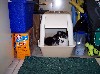
Front view of the radius arm tipping with tbar arm down:

Rear view with tbar arm still down. You can see it looks less tipped only because the distance from where we are looking is closer to the bearing:

Front view of radius arm tipping with tbar arm up:

And finally, rear view with tbar arm still up:

By putting a spherical bearing out at the end of the radius arm, the whole system just gets much smoother and there is little to no loading on the radius arms at all (especially the stem that slips into the rear bushing). The only things that sees "stress" if that's what you want to call it, is in the tbar arm. It will twist a little, and bend slightly to compensate for the length change due to the radius arms path, relative to the torsion bar arm. And, lucky for us, the tbar arm is designed to do just that. So I think everything is good. The tbar arm will bend back about 0.020" at the ball joint, and twist less than 2 degrees with this type of setup. The radius arm, especially the rear stem part of it, will see much less stress when it tips in it's shiny new spherical bearing.

Unrelated side note: Because of the natural tipping of the radius arm in a system like this, I think you can see why I was so concerned before when I read that people where using solid Delrin bushings at the rear radius arm stem joint. I am still afraid that stem will see too much stress due to the natural tipping of the radius arm in that type of a system. Those Delrin bushings are trying to prevent the radius arm stem from tipping.

And that arm need to tip.
Whew! Did I do it? I hope I was clear enough that you guys and gals have a better idea of what I'm seeing here. Like I said above, I just know that if you where standing here, you would see what's really going on, and I think you would approve.

Take care all!
David
P.S. My most sincerest apologies to J (kakabox) for being so gosh damn confusing!
 Sign In
 Create Account


 View Garage
 Back to top