Jump to content


H22 Crx Project


  • You cannot reply to this topic
230 replies to this topic

#1
firstgencrx

  • This thing should fit!
  • PipPipPipPipPip
    • Group: 2013 Contributor
    • Location:opɐɹoloƆ 'suılloƆ ʇɹoℲ
Note: Table of Contents at the bottom of this first post.

Hello all!

I'm re-starting my personal build project. In fact, this is the THIRD time I've tried to have a build project. The first project was way too ambitious, so I started a second one that was more manageable. Then my second project thread got hosed because I lost my pictures. It's too much work to try and repair the second thread, so I'm hoping you guys and gals will let me have a "Do-Over!." I'm going to try and learn from the originals and try and make this one simpler and cleaner. I'm also taking clues right from the master play-book on how to do a good build thread. I'm talking about the master himself, kakabox! I can only hope my build thread will get 1/100th the interest his does. I'm also hosting my images in a safer place, so this build thread should stay alive. wink.gif

Most of you know about my project already, so you can ignore these first few days of posts and check back when I start to do some new stuff. I will not post up a lot about what I have already done, but I will be as detailed as practical for the rest of my project. Lucky for you and me, my project is not very far along, so there's lots to do. I expect this build thread to be a long one.

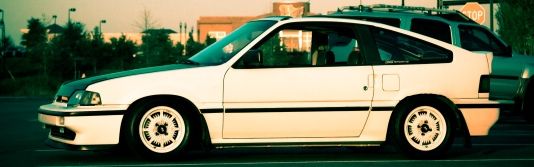
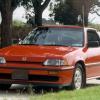
I had second thoughts about re-naming my personal project the "H22 CRX Project" because I'm afraid some of you might think this is a good idea. Believe me, it's not. My choice for the engine was not a smart one. I would have been much better off doing a B series or D16. If I could start the project over, I would not use an H22. But the H is what makes my project unique, hence the reason for the new project name. So how in the heck did I chose this engine? Well....

I actually started my project about 6 months before I even new this RPR place existed. I didn't have the great resource of RPR to educate me on what fits and what doesn't. In the beginning, I just researched all the Honda four bangers, and I personally felt the H was the best choice. It was cheap, has gobs of torque, and great aftermarket support, something we can't exactly say about the rest of our little cars. I am a big fan of torque. For the street, there is nothing more fun to drive. Cars that have all their power on the top can be fun too, but not all the time.

I got my hands on a JDM H22 BB4 pulled from a 93 Prelude. It has a five speed, but not the LSD version. It has a claimed, at the crank, 197 HP @ 6,800 RPM, and 161 ftlb torque @ 5,500 RPM. For the money, I calculated this was the best bang for the buck. Little did I know what I was getting into! blink.gif

But before we get into the engine, I need to show you the most important tool I purchased before I started my project. When I saw this on Ebay, I knew I had to have it! laugh.gif


Armed with the ability to tell the time, but having no frigging clue how long this will take, I began my journey. cool.gif

Next up, the second most important tool I built for this project. The rotisserie....... I'll continue tomorrow. tongue.gif

Take care all!

David

Table of contents

Introduction:
This first post

Special Tools
1. The Rotisserie: Post #7, or this link Rotisserie

Tips & Tricks
1. How to regain your memory: Post #30 or this link How to regain your memory

Motor Mounts
1. Positioning the engine: Post #12 and #13, or this link Positioning the engine
2. Drivers side mount: Post #14, #15, and #16 or this link Drivers side mount
3. Passenger side mount: Post #20, #21, and #22 or this link Passenger side mount
4. Rear cross member mount:

Engine
1. Custom Oil Pan: Post #149, #153, #154, and #167 or this link Custom Oil Pan
1. Oil Pickup Mods: Post #200, #201 or this link Oil Pickup Mods

Front Suspension
1. Knuckle cleanup: Post #29 or this link Knuckle cleanup
2. Sub-Frame Alignment: Post #62 or this link Sub-Frame Alingnment
3. Sub-frame reinforcing:
4. Torsion bar arms spherical bearings: Post #54 and #55 or this link Torsion Bar Spherical Bearings
5. Radius arms spherical bearings: Post #56, #57, #58, #60 and #61 or this link Radius Arms Spherical Bearings
6. Traction bars: Post #67, #68, #69, #70, #76, #77 and #78 or this link Traction bars
7. Caster/Camber plates:
8. Custom front sway bar:

Rear Suspension
1. Axle cleanup:
2. Two-axis panhard bar:
3. Rear trailing arms spherical bearings: Post #52 and #53 or this link Rear Trailing Arm Shperical Bearings

Chassis
1. Front fender truss braces: Post #117, #118, #119, #131, #132, #137 and #138 or this link Front Fender Truss Braces

Electrical

1. VSS:
2. Cluster mods:
3. Chipping ECU:

Sharing with others what I do for myself!

My H22 CRX Project

Posted Image

#2
Lymitliss

  • King Luke
  • PipPipPipPipPip
    • Group: 2012 Contributor
    • Location:Seattle, Wa
    • Drives: 1986 CRX Si B18C1, 1973 240Z V8 Conversion
    Garage View Garage
This promises to be a very exciting project! I look forward to keeping up with the build! Goodluck with everything!
Build Thread- Here


#3
DEBTsE-at

  • LeftHandShifting!
  • PipPip
    • Group: Members
    • Location:Cali
    • Drives: Wonder E-at
Glad you chose to start your build again wink.gif ... SUBSCRIBED!
...inDEBTwithGOD...MUGEN///POWER...

#4
Old School REX

  • ホンダ、夢の力
  • PipPipPipPipPip
    • Group: 2012 Contributor
    • Location:Nashville TN.
    • Drives: -------- 1986' CRX Si (X2) -------- 1993' GMC Sanoma SLE
    • Image Gallery
+1^ biggrin.gif Good thing to see you have your priorities straight with that clock there too buddy. Good luck!

#5
ChrisF-dude

  • Powered by Natural Gas
  • PipPipPipPipPip
    • Group: 2010 Contributing Member
    • Location:Maryland, United States of America, Earth, Terran System, Milky Way 21158
    • Drives: 85 CRX Si (ZC), 2011 Toyota Camry
    • Image Gallery
I got that clock a couple years ago, really neat. Just becareful, as it runs fast when Vtec kicks in.

Once a woman is introduced to Colonel Angus, she'll settle for nothing less.
chrisfpixelcrx.jpgSiemblem.jpg


#6
Lymitliss

  • King Luke
  • PipPipPipPipPip
    • Group: 2012 Contributor
    • Location:Seattle, Wa
    • Drives: 1986 CRX Si B18C1, 1973 240Z V8 Conversion
    Garage View Garage
QUOTE (ChrisF-dude @ Jan 9 2010, 10:53 AM) <{POST_SNAPBACK}>
I got that clock a couple years ago, really neat. Just becareful, as it runs fast when Vtec kicks in.


Ha! Good one!
Build Thread- Here


#7
firstgencrx

  • This thing should fit!
  • PipPipPipPipPip
    • Group: 2013 Contributor
    • Location:opɐɹoloƆ 'suılloƆ ʇɹoℲ
The rotisserie

The car for my project actually belongs to my wife. It's a 1984 1.5L carbed model. Red body with silver bumpers and lower plastic. The car was warn out. It seemed that everything on the car was broken or soon to be. So I knew I would be pulling it apart. Completely. Probably the only good thing about this car was that it was from California. Very little rust. wink.gif

I'm older, and I am not a mechanic. The thought of spending months on my back lying on the floor was not my idea of a good time. So I put together a rotisserie. I made it super heavy so I can use it on future projects. I estimate the weight of the rotisserie at or near about 1,400 pounds. Made from mostly 4" and 3" quarter wall material with some 2" by quarter wall for grips and bracing. It can easily hold a vehicle that is 5,000 lbs or more.

I built it so that it can pick up a car for mounting. Most rotisserie designs are fixed height off the floor. What that means is you need to pick up the car somehow to get it into the rotisserie.

End view:


The hand crank at the top is there to change the distance between the grips and the center of rotation. This allows you to move the rotation of the rotisserie to the center of mass:


Then a hydraulic jack at both ends allow you to change the hight of the center of rotation. This is what I use to pick up the car. Even made a simple safety system just in case the bottle should start to leak:


Shot of the pivot. That's a 5" diameter solid steel shaft in there:


And how it guides itself on some UHMW block bearings:


How my grip arms attach to the rotisserie:


And an example of how the grip arm grabs the car. I just grab it in four places, the bumper mountings:


The distance between the rotisserie end is simply changed by using different length 3" by 1/4" wall tubes that run the lower length of this contraption!:


Parting shot:


Next up: The long process of creating motor mounts, or "Why you should never consider putting an H22 in a 1G CRX!" laugh.gif

David
Sharing with others what I do for myself!

My H22 CRX Project

Posted Image

#8
kakabox

  • Turd Polisher
  • PipPipPipPipPip
    • Group: 2012 Contributor
    • Location:Seattle, WA 98115
    • Drives: from point 'A' to point 'B' daily.
    • Image Gallery
    Garage View Garage
QUOTE (firstgencrx @ Jan 9 2010, 04:23 PM) <{POST_SNAPBACK}>
The rotisserie

David

I said it before when I first saw it...that is the most awesome rotisserie I've ever seen. [Do you have plans I can buy?]

It's good to see you posting in your project blog again, even if you're just re-creating the beginning. It's still great viewing!

Subscribed. smile.gif

#9
firstgencrx

  • This thing should fit!
  • PipPipPipPipPip
    • Group: 2013 Contributor
    • Location:opɐɹoloƆ 'suılloƆ ʇɹoℲ
QUOTE (kakabox @ Jan 9 2010, 06:45 PM) <{POST_SNAPBACK}>
I said it before when I first saw it...that is the most awesome rotisserie I've ever seen. [Do you have plans I can buy?]

It's good to see you posting in your project blog again, even if you're just re-creating the beginning. It's still great viewing!

Subscribed. smile.gif


Thanks J! I feel lucky and honored you approve. wink.gif

No design on the rotisserie. I literally built it from my head. On the fly sort of speak. Started at the bottom and worked up. tongue.gif
Sharing with others what I do for myself!

My H22 CRX Project

Posted Image

#10
Old School REX

  • ホンダ、夢の力
  • PipPipPipPipPip
    • Group: 2012 Contributor
    • Location:Nashville TN.
    • Drives: -------- 1986' CRX Si (X2) -------- 1993' GMC Sanoma SLE
    • Image Gallery
For the most part it looks like a very simple design though; aside from the little things that make yours so nice like the lubrication points on the crank and the crank mechanism itself. And from your pictures alone I would wager that anyone with the proper know-how could make one for themselves. (Even if it wouldn't turn out nearly as nice!) The only part I am a bit confused about personally is the pivot point and the bearing system used.

Either way, I am very excited about seeing the process of fitting the H22.... again... laugh.gif

#11
greasemonkeyreborne 5x1g's

  • Leadfoot
  • PipPipPipPipPip
    • Group: 2018 Contributor
    • Location:Foreign national in TX
    • Drives: 9 crx's: #1 228k 87si beater, #2 concours 25K, #3 108K 87si, #4 98K parts car, #5 213K 87si parts car, #6 84 straman, #7 86si 150k #8 67k parts #9 129K si for straman conversion
Holy Crap! that rotissari idea is great. I havent' been on all that long and must have missed the earlier posts on your project.

Very, very clever.

Good luck and I hope you stay w/ this one

Dave
Keepin' it OEM

#12
firstgencrx

  • This thing should fit!
  • PipPipPipPipPip
    • Group: 2013 Contributor
    • Location:opɐɹoloƆ 'suılloƆ ʇɹoℲ
Positioning the new engine

By the time I was ready to start building motor mounts, I had been here long enough to realize I was in for some work. But my ego was to big to admit defeat, so I charged on. tongue.gif

I took many measurements, and determined that the engine and transmission combination doesn't fit. It's simply too long. My goals where to position the engine so it had stock or better ground clearance, didn't stick up so high that the hood wouldn't close, and get the axle outputs from the transmission such that the axles where not too bent.

It's important to get your axle lined up, but not perfectly. CV's and traditional drive shafts need a little bend in them for the longest life. The joint needs to work a little when you are driving to keep the grease moving around. If the axle is perfectly straight, the grease leaves the joint and it wears out too soon. With too much mis-alignment, the joint works too much. You need just a little mis-alignment. I know it sounds un-intuitive, but the joint needs to work a little to last the longest.

Thanks to my trusty rotisserie, I was able to take my time, and figure it all out. One of the nice things about my contraption, is I can raise and lower, or tilt the car in small increments. I started by simply placing the engine and transmission combination on a rolling appliance cart. I carefully blocked it up on the cart so that it was level, and tilted back at an angle:


I lowered the car and started to get a much better view of what I was in for. Top view:


Drivers side view:


Passenger side view:


Once the car was lowered as low as it could go, I could see more clearly the fit problems. The first thing I needed to address is the frame rail on the passenger side. Even when the engine was positioned as far as it would go on the drivers side:


the transmission was still protruding under the passenger side frame rail:


The engine can't be raised anymore without hitting the bottom of the passenger side frame rail:


The engine was still way too low in the chassis for any real ground clearance, so I needed to raise it up somehow. The axles where also much too low:


After some calculating, I figured out that I needed to make some deep notching on the bottom of the passenger side frame rail for transmission clearance. This would let the engine come upward, giving the transmission a place to go. So I did some initial marking. A little hard to see:


But before I cut away on the frame rail, I first need to reinforce it. Put the extra structure in, then cut out what you don't want. Keeps things happy that way. tongue.gif

Continues in next post.....
Sharing with others what I do for myself!

My H22 CRX Project

Posted Image

#13
firstgencrx

  • This thing should fit!
  • PipPipPipPipPip
    • Group: 2013 Contributor
    • Location:opɐɹoloƆ 'suılloƆ ʇɹoℲ
Positioning the new engine (part two)

I chose to put a rail just above where I would notch out the bottom of the frame. I started with a piece of 1.75" by 0.120" wall steel square tubing. I started to shape it by cutting the ends on an angle:


I finished it off by putting a slight bend in it, and capping the ends. The shape fit perfectly on top of the frame rail:


I then just literally welded it in. The welding was on top of the frame rail and the fender well. This shot shows it not welded yet, but put in place:


With the frame structurally sound, I can now cut out the bottom of the frame for transmission clearance:


Later when I do the passenger side mount, I reinforce this side even more.

Next I re-lower the chassis down over the engine/transmission assembly, and check for clearances (I love this rotisserie!):


Much better. I was able to get the engine low enough to give me the same ground clearance the original EW had. Even the axles where lining up in a better position:


It was interesting to note, the frame rail is a real composite of many layers. Tougher than it looks from the outside:


Now that I've got my engine positioned where I want it, it's time to start making mounts!

Next up, Drivers side mounts. But that's for another day. cool.gif

Take care all!

David
Sharing with others what I do for myself!

My H22 CRX Project

Posted Image

#14
firstgencrx

  • This thing should fit!
  • PipPipPipPipPip
    • Group: 2013 Contributor
    • Location:opɐɹoloƆ 'suılloƆ ʇɹoℲ
Drivers side mount

After getting the engine positioned where I wanted it, I started to build some mounts. The drivers side mount to be exact. The original drivers side engine mount used in the Prelude came off the center of the cam gear side of the engine block. I wanted to use the original CRX drivers side frame mount. This meant I needed to create something that would bolt to the front of the block. The B series engines are mounted in our cars like this too.

I did not plan this mount at all. So don't be surprised at how complicated and strange it is. I knew I would never mass produce something like this, so I just let it happen!

I first chose the four bolts I would use for the block end of the mount. I chose these because they where located level with the frame mount. The mount started with four steel bushings:


Three are short, and one is long. I did this for reasons you will see later tongue.gif :


I then machined up a plate that would fit over the bushings:


Fits! Amazing:


Next, I machined a tube to reach out in front for more structure. I start with a slug of solid round stock:


I decide to taper it for strength. Remember, I'm flying blind here, no real planning at all:


Looks cool enough. I must be doing something right:


Next I anticipate a hole in my block plate is in order:


And I then tack weld the plate to the bushings:


So far so good! Now the engine tilts back 6.5 degrees. Originally it tilted back 9 degrees in the prelude, but I needed to lose 2.5 degrees to make it work in the CRX. This causes a small oil pan problem, but I'll deal with that later. But what I'm getting at is the cone I just made needs to be cut on an angle where it fits to the block plate. 6.5 degrees to be exact:


Continued in next post.....
Sharing with others what I do for myself!

My H22 CRX Project

Posted Image

#15
firstgencrx

  • This thing should fit!
  • PipPipPipPipPip
    • Group: 2013 Contributor
    • Location:opɐɹoloƆ 'suılloƆ ʇɹoℲ
Drivers side mount (part two)

With the end of the cone angled, I build a simple welding fixture to weld it to the block plate without warping everything. Notice the notch for one of the bushings:


Everything is welded up on the front. Remember the longer bushing?:


And weld up the back:


Bolt it on. Hey, it still fits!:


At this point, I break out and make the outer shells and inner bushings for the polyurethane mounts. I make all three the same size for convenience:


I also machine up some solid aluminum inserts only for mock-up:


Bolt the future poly end in the original frame mount. Now I need to reach out from the taper, to the frame mount:


I start with some 11 gage side wings:


One for each side. I bend one to make the thing a little stronger:


I make a top and bottom plate to finish the box:


Continued in next post....
Sharing with others what I do for myself!

My H22 CRX Project

Posted Image