Headlight Air Intake (HAI)
WARNING: This is the "mother of all" Kakabox blog posts...so ya better grab a beer and get comfy!
I decided to make a Headlight Air Intake (HAI) as a means to shove as much air into the airbox as possible in the hopes of improving the flow efficiency of the air intake and possibly a power increase. To accomplish this, I took advantage of the proximity of the air box to the rhs headlight.
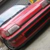
Here's the goal: to provide as much cool dense air as possible to the airbox through the headlight opening...
Possible Ram Air Effects? If headlight area is a high pressure zone, air from a headlight scoop would be pushed into the airbox, building up in behind the panel filter - creating a static pressure greater than ambient which would then feed airtube, then the intake manifold. This increase in air delivery efficiency and denser intake charge could then provide increased engine power. In theory, anyways.
However, I'm not sure that the 3g headlights are in a high pressure zone. It could be that the bumper trips the air up and over the headlights, perhaps creating a low pressure zone at the headlight face. I really don't know; I'm making no claims of any ram air effects. At least the air box will now be open to a large supply of cooler ambient air.
Arguably, this mod is a lot of work for questionable gains. However, I really like to make stuff...esp. for the Kakabox! I just can't leave well enough alone and have to be constantly fiddling w/the 'turd' (you guys don't seem to mind...right?). In addition, after trying my hand at making a fiberglass airtube for the upstream side of the airbox, I naturally had to address the downstream end and make a HAI!
Aesthetically, the design goal was to make the headlight intake to look similar to the OE headlight. In other words, at casual glance, someone may think it was a headlight and not notice it actually was an air intake. I wanted the outside of the scoop to have the same general contours as the OE headlight. This design criteria complicated the build, but I think it was worth it.
I started by modifying the OE headlight bracket...the horizontal "pan" that the lower trim piece attaches to. This trim piece has the same curvature as the headlight. I captured this curvature by tracing it onto a sheet of 1/8th inch steel.
I then drilled and tapped the strap for #8-24 stainless steel button head fasteners that'll be used to attach the air duct and cover screen to headlight frame, and the frame to the pan. I did not want to use any nuts for this, that's why I selected 1/8" steel which I could weld (I don't do aluminum) and tap threads into. This strip of steel captured the lower fwd contour of the headlight. I cut up the strip to make 'tabs' to lighten the design; don't need the steel for anything btwn the fastener locns.
I used 5/16 inch diameter steel brake hydraulic tubing to construct the headlight scoop 'frame'. It's cheap, light, is easily bent, and I can weld it!
I cut a section to make the lower portion of the frame, bent it to match the lower headlight contour then welded it to the tabs. The cardboard under the tabs is to simulate the thickness of the fiberglass scoop that will attach there.
I cut and bent another tubing section for the vertical piece of the frame to capture the headlights curvature where it meets the corner light. Aluminum speed tape is used to protect the corner light lens from weld splatter...
Using the same process, I captured the headlights upper and inbd edge contours...
...HAI Build continues next post:
33
The Kakabox Build
Started by kakabox, Sep 23 2005 04:31 PM
2000 replies to this topic
#1651
Posted 31 October 2009 - 01:07 AM
#1652
Posted 31 October 2009 - 01:08 AM
...HAI Build continued:
For a better fit and weld, I had used a round file to 'fish-mouth' the tubing...
Once I had captured the headlight's perimeter curvature, I made more mounting tabs. After drilling and tapping holes for the duct and mesh attachments, I welded them to the frame...
Done! Now I had a 'frame' to which I could attach the air scoop and the wire mesh cover.
To make the air scoop, I employed same the mold-less composite layup technique used to make the airtube (read: Paper Mache' using 6 oz. fiberglass cloth and epoxy resin). This time around, to make the 'buck', I used Styrofoam instead of the floral foam I had used for the airtube. I found the Styrofoam much easier to work with. It isn't as delicate to handle and more resistant to denting & gouging during shaping. In addition, the packing tape used to cover the foam actually stuck to the Styrofoam as opposed to not; that was a huge improvement in the process. Also, using Styrofoam has the advantage of being dissolved by acetone which makes removal of the foam buck much easier (as you will see).
I started making the foam buck by literally sticking the frame tab side down into a block of foam. I then shaved the foam away from the frame leaving the tabs exposed. This ensured that the fiberglass scoop would slip fit onto the frame tabs.
Then I covered the frame w/packing tape and mounted it to the headlight bracket.
I continued to glue on blocks of foam and shaped them to fit within the confines of the bracket. I ended up with this...
To cram all the air the headlight scoop would collect into the airbox, I needed to enlarge the OE airbox snorkel opening. I cut a 4 inches in diameter circle into the airbox:
Installing the HAI module showed me how much of a gap I had to bridge for the scoop to go directly into the airbox...
I glued more foam on until the scoop extended into the airbox...
...HAI Build is continued next post...
#1653
Posted 31 October 2009 - 01:09 AM
...the HAI Build continues...
After final shaping...
Covered in packing tape, I applied 3 coats of Meguire's #26 wax as a release agent. I then stuck a long dowel into it to allow for easier handling...
Using 6 oz. fiberglass cloth and epoxy resin, I applied 3 layers, 4 layers where the duct attached to the frame tabs. I used a nifty roller to roll out the bubbles and distribute the resin...
...done!
Since I used Styrofoam, which dissolves in acetone, removing the foam buck was easy. I poured ~1/4 cup of acetone in one end...another 1/4 cup in the other...let the foam dissolve then pulled the gooey mess out!
...HAI Build continued next post:
#1654
Posted 31 October 2009 - 01:09 AM
...HAI Build continues...
To capture the frame attach locns, I back-drilled through the tab holes while the duct was still 'stuck' on the frame:
Since I had put several coats of mold release wax on the packing tape, the tape pulled right out of the inside of the duct (I used Meguire's 26 Yellow Wax for a 'mold release' wax). Separating the frame from the duct was a little more difficult, however, using plastic putty knifes I was able to gently pry it off.
Next step...making the wire mesh duct cover. I wanted more of a finished look. I did not want the duct screen to look like I just ran to Home Depot and got some 'chicken wire' and slapped it on. I wanted something a little nicer. To that end, I bought stainless steel wire mesh from McMaster Carr:
http://www.mcmaster....238t521/=4alj0y
I spent a fair amt of time working the mesh over the frame. I used Vice-Grip flanging pliers to make a 90 deg. bend for the bottom tabs, attached it to the tabs, then wrapped it around the frame to the top. I was careful to align the mesh 'grid' with the frame tubes...neatness does count!
The very hardest part of this build was the looping and crimping of the cut wire ends. The wire mesh is woven, like cloth. You could 'unravel' the weave just by pulling out individual wires. So I looped and crimped each cut end so the mesh would stay together. This was very repetitive and hard on my hands; it took about 4 hours total to finish the screen's edges in this way. For my efforts, I ended up w/a pretty good bout of carpal tunnel syndrome the next day! It has since gone away.
...HAI build continued next post (OK, last one, I promise!)...
#1655
Posted 31 October 2009 - 01:09 AM
...HAI Build, last post!..
After painting the frame and the bracket, all the parts got together for a photo op!
Here's the finished HAI 'module'. It's all self-contained and swaps out easily w/the headlight...well, you do have to remove the header panel first, but, that only takes a few minutes w/a Phillips head screw driver and a 10 mm socket. The aluminum straps are stabilizing straps since the frame/duct is cantilevered off of the headlight bracket...
Top
Back
Bottom
FINALLY! Installed...
Where the air goes...
All back together...is it a headlight?
Or...a Headlight Air Intake?
That's it...you made it through...hope it was worth the journey!
Cheers!
#1656
Posted 31 October 2009 - 01:28 AM
Now, how about a similar mesh cover for the other headlight, and for the stock replacement as well.
Regarding aerodynamics, the mesh may have a not so nice effect at high speed (50+MPH) because the air tends to flow over, rather than through, at that point. Your RPM/Speed combination may have a strange effect on how well your setup works with the mesh in place. In other words, you may actually need to be pulling some vacuum to see any effect at all from the new intake.
Of course, I could be completely wrong, too. Maybe the holes are big enough to not disturb through-flow at speed.
How about we just agree to respect each other's opinion?Even though yours is so obviously wrong...
Click here to see how I basically gave my car away to another RPR member!
#1657
Posted 31 October 2009 - 01:31 AM
#1658
Posted 31 October 2009 - 02:13 AM
WOW!...is there anything you cant do?.. lmao
i love the hole kaka project!...
#1659
Posted 31 October 2009 - 09:38 AM
Nice work J, looks really good. Nice idea about using the styrofoam too, I hadn't even thought about that. Looked at it a few times since it sits right next to the floral foam at Wally World but never thought about the reaction difference under the acetone. The larger pieces open up lots of new possibilities too!
I know what you mean about the SS wire mesh! The stuff is great for things like that (and grill openings) but does take some work once you cut it.
Jay
I know what you mean about the SS wire mesh! The stuff is great for things like that (and grill openings) but does take some work once you cut it.
Jay
If you love the Elise, drive a Se7en - Caterham or whatever...
It has even less content than the Elise, is less graceful looking
...and changes direction like a ping pong ball whacked by Thor.
#1660
Posted 31 October 2009 - 12:42 PM
QUOTE (Christ @ Oct 30 2009, 11:28 PM) <{POST_SNAPBACK}>
Regarding aerodynamics, the mesh may have a not so nice effect at high speed (50+MPH) because the air tends to flow over, rather than through, at that point. Your RPM/Speed combination may have a strange effect on how well your setup works with the mesh in place. In other words, you may actually need to be pulling some vacuum to see any effect at all from the new intake.
Of course, I could be completely wrong, too. Maybe the holes are big enough to not disturb through-flow at speed.
The mesh I choose has a 74% open area...but the amount of surface area covered is fairly large. I think there is enough flow area to compensate.
You have a very good point about the air flowing up and over the headlight assy at higher speeds. My assumption that the headlight area is a high pressure area at speed may not be correct. The correctness of this assumption will have more of an effect on the HAI flowing air into the airbox than the mesh open area.
QUOTE
This DaimlerChrysler graphic shows the typical frontal pressure distribution of a car.Looking just at the bonnet you can see that there is low pressure(blue)where the air wraps around the leading edge of the bonnet,grading to high pressure(green)as the air reaches the obstruction which is the windscreen.
Ref. http://www.msprotege...mp;postcount=13
This graphic seems to show the headlight area in a high pressure zone. Look at the rhs where the pressure gradients are shown; the colors look similar to the lower windshield area which is a high pressure zone. I have no idea of the airspeed or any of the other parameters used to generate this graphic so, take it w/a lump 'o salt! I know it's not a 3g Civic frontal pressure distribution and that the 3g's distribution will be different. In comparison, there may indeed be a low pressure zone around the 3g headlights.
My thoughts going fwd w/this mod was that I going to provide the airbox w/a greater amount of cooler, denser air than from where I was getting the air before: from the fender well thru a much smaller snorkle w/a 90 deg bend in it...
Intuitively, I think the HAI does provide an improvement in the flow and amount of air provided to the airbox. However, I'm finding out that when it comes to aerodynamics some things are not always intuitive!
It is what it is...we'll see how it works in reality. One thing is for sure...my night time illumination just got cut in half!
Cheers!
#1661
Posted 31 October 2009 - 09:01 PM
QUOTE
It is what it is...we'll see how it works in reality. One thing is for sure...my night time illumination just got cut in half.
Question is after all that nice fab work are you street legal to get from A to B to race? Since I skimmed a lot of this I didn't notice if this was a system to "in and out" at a meet and still run proper lights to get home in the dark. JS
If you want one of these Logos send me a PM
Austin Mini Van with DOHC Honda HP
http://www.angelfire.com/droid/strudel
Honda reliability and power combined with Mini cachet and style.
#1662
Posted 31 October 2009 - 09:15 PM
#1663
Posted 31 October 2009 - 11:09 PM
QUOTE (strudel @ Oct 31 2009, 07:01 PM) <{POST_SNAPBACK}>
Question is after all that nice fab work are you street legal to get from A to B to race? Since I skimmed a lot of this I didn't notice if this was a system to "in and out" at a meet and still run proper lights to get home in the dark. JS
Hey Jerry!
I believe I'm still street legal...in the daylight hours! However, I'm sure an officer could find multiple citations if he wanted to, even in the day. I drive in a manner not to attract attention.
The HAI is modular and can easily be swapped w/the headlight at the track. A 10mm socket, nut driver, phillip head screwdriver and 20 mins is all you need (you have to remove the header panel).
I've never driven home in the dark from the track, ever. Typically in the Spring/Summer, I leave around sunrise, so I do NOT need to use the headlights. In the Fall, when sunrise comes later, I do have to use the headlights when I drive to the track that's 90 miles away. If I was going to Pacific Raceways, which is only 40 miles away, I can leave house later, right around sunrise, and not have to use them.
...and what's this "skimmed a lot of this" stuff? And here I though you read every word of the Kakablog.
QUOTE (OG Wagon @ Oct 31 2009, 07:01 PM)
Your fab. work = Un-flippin' real dude!
I like your equation...
Thanks.
#1664
Posted 01 November 2009 - 12:35 AM
QUOTE
...and what's this "skimmed a lot of this" stuff? And here I though you read every word of the Kakablog.
I do read it all, usually! But I was away a couple of days and will do a read over when there is more time and try and figure out what you really said. JS
If you want one of these Logos send me a PM
Austin Mini Van with DOHC Honda HP
http://www.angelfire.com/droid/strudel
Honda reliability and power combined with Mini cachet and style.
#1665
Posted 01 November 2009 - 04:38 AM
You could always rig up a quick release, or easily removable, fog light or driving light to replace some of the light lost from the passenger side.