Sign In
 Create Account
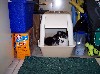


 View Garage
I installed Energy Suspension urethane rear trailing arm (ta) bushing in the Kakabox a couple of years ago...
http://www.redpepper...e...st&p=241331
http://www.redpepper...e...st&p=264990
I've run them a for a couple seasons and they seems to work ok, at least they don't squeak! However, one thing I do not like about them is they don't allow the trailing arms to rotate freely. The rotation of the trailing arms binds in the urethane bushings. I noticed this when I installed the bushings. The arms did not pivot freely at all; they bind in the attach clevis...and, FWIW, the OEM rubber bushings bind as well.
I don't believe the rear suspension can work optimally w/the control arms binding in their pivots. I think the car's handling is more precise, consistent, and controllable when the suspension doesn't bind and is free to articulate. So as soon as I had installed the ES bushings, I started thinking about a fix for the bind (actually, I knew exactly what to do as I had installed rod-end front and rear lower ta's on my '90 5.0L Mustang).
Then, one day I saw the old 3g Civic Mugen catalog in jsgprod's pic gallery... http://www.redpepper.../v/gprodn/MUGEN [kudos to jsgprod for putting it in his gallery]...I became inspired when I saw this page:

Trailing arms w/rod ends, freely pivoting rod ends! Nice. From looking at the picture, it 'appears' Mugen just cut off the OE rubber bushing and welded in a threaded insert for the rod end. I decided I could do the same and make my own...right in the little 'ole Kakashop!

Here's how I made the Kakabox version:
First I spent $20 and 1 hour at the local Pull-A-Part and pulled a pair of 3g trailing arms from an '84 Civic:

Before I started cutting up the OE trailing arms, I made a simple 'jig' to capture critical geometry. I wanted the center of the rod end to be in the same location as the center of the OE pivot in the fore-aft direction and also in the inbd-outbd direction.


Using the 'D' hole feature which is common for both the lh and rhs arms, I screwed a delrin bushing into a block of wood. That allowed me to located pivot center relative to that feature. I drilled a hole for the OE pivot bolt and shimmed the arms w/wood until level.
I had some OE trailing arm pivot bushing sleeves which I measured to find the centerline of the OE arm pivot bushing. The OE bushing (and hence, the chassis clevis) is ~2.25" long.

The centerline of the plate that makes up the trailing arm at the bushing is one half that...or 1.25"

So now I know the distance from the base of my 'tooling jig' to the center line of the rod end... 1.25"

I've captured the OE trailing arm pivot's fore-aft and inbd-outbd centerline locns w/the jig.
My idea is to cut off the OE rubber bushing and form a "slot" using the existing lightening hole...like I have marked in red here:

I measure the width of the slot at ~1.20". My idea is to 'wedge' and weld in a threaded insert in this slot...threaded for a male rod end. Because I could easily open the slot up to 1.25" across, and because the stiffening pocket in the arm prevented a centered weld on a cylinder, I decided upon using 1.25 x 1.25 square 1018 Mild Steel bar stock. I bought four 1.75" long sections (cut to length) from a local metal store: http://www.onlinemet...amp;top_cat=197

...to be continued...

 Back to top