it was modified very much like the one you have done. I didn't do it, and I don' t remember for sure. but i believe they had basically just hacked the conflicting gusset right off. I don't think it really created a stress riser for crack propagation, I think it just dramatically decreased the torsional stiffness and the steel fatigued.
the rubber did not fail, nor did the shell, just the support bracket. it basically just ripped the bracket off of the shell. Leaving a significant piece of the gusset on there with a nice radius on the corner like you did will certainly be much better than mine was.
is there room to add another gusset on the underside?
Steel (or any other metal that I know of) cannot "fatigue" w/o a stress riser present and a crack/s formed. Structures fail in fatigue due to cyclic loading causing
existing stress risers to form cracks which then propagate over time until the stress due to loading exceeds the strength of the remaining section area. How quickly this happens is due to many parameters, the main ones being how big a stress concentration (Kt) there is, the magnitude and frequency of cyclic loads and the material...but fatigue failure always involves a stress riser (and crack) of some kind. Even if you can't see one w/the naked eye, they are there, hence, for fatigue life, surface finish and corner radii are very important.
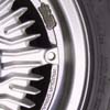
I can't really see a torsional failure w/o the rubber failing first. That would mean either the torsional stiffness of the rubber exceeded what was left of the steel bracket (after the hack job), in other words, the load twisted the steel bracket instead of the rubber insert. Or the mounting bolt bottomed out in the shell...like the screwdriver in this pic:

...and twisted the shell off. I just can't see it physically possible for the mount bolt to deflect that much, unless there was something else going on besides the alterted mount. Like maybe a failed or disconnected rear center mount, or cracked/damaged welds on the mount. Or maybe loose mounting bolts...?
I would think a "dramatic" loss of torsional stiffness in the steel support bracket would of been noticable and able to be felt. Look at the pic above again...that's a torsional load applied to the mount. Are you saying that the remaining steel bracket's torsional stiffness was less than the rubber? If that was the case, I would think you would be able see and feel that long before you experienced mount failure.
There appears to be room on the underside to weld on another gusset. However, careless welding of a gusset might create other issues. Like melting the rubber insert and/or causing a heat affected zone that could be a stress riser too.
IMO, an additional gusset is not needed if the mount is clearanced "properly".
 Sign In
 Create Account
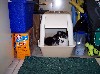


 Back to top
 View Garage