Jump to content


The Kakabox Build


  • You cannot reply to this topic
2000 replies to this topic

#736
DarkHand

QUOTE (rollz87civic @ Feb 12 2007, 01:06 AM) <{POST_SNAPBACK}>
left hander's are way cooler than right hander's


^--- Completely true
DarkHand

#737
kakabox

  • Turd Polisher
  • PipPipPipPipPip
    • Group: 2012 Contributor
    • Location:Seattle, WA 98115
    • Drives: from point 'A' to point 'B' daily.
    • Image Gallery
    Garage View Garage
QUOTE (D Jaws II @ Feb 11 2007, 10:00 PM) <{POST_SNAPBACK}>
I just have to remember to find one BFH.

BTW, you a lefty?
Donnie

I think I picked up the 3 lb. mini sledge at Home Depot years ago. It has a nice short handle which makes it easy to swing w/one hand. I originally bought it when I built my deck and found I couldn't swing a 16 oz. framing hammer hard enough between the 16-on-center floor joists to drive the nails in. I found that if I turned the mini sledge to use the side of the head, I could get a long enough swing w/enough mass behind it that the nails couldn't resist the force and buried themselves in fear! laugh.gif

Sorry to disappoint...I'm a righty...I need my right hand to hold the camera! All the hand shots are staged. ph34r.gif

#738
DEIVIONCRX

  • Demon Of All Trades
  • PipPipPipPipPipPip
    • Group: 2013 Contributor
    • Location:Oklahoma
    • Drives: 87 Civic Si, 88 Civic DX, 90 CRX DX, 80 Trans Am, 10 Fit Sport
    • Image Gallery
    Garage View Garage
Do you have 3g Civic and 1g Teg Hubs, laying around?, if so could you measure the OD on them, i put new wheel bearings in my 3g Knuckles about a year ago, and id realy like to just pull out the 3g Hubs, and press in the 1g Teg Hubs, in order to run the B-series Axles, for my LS Swap. Insted of swaping the whole Teg Knuckle, and either buying new wheel bearings or trying to press out the good ones and press them back in the Teg's.
Posted Image

#739
kakabox

  • Turd Polisher
  • PipPipPipPipPip
    • Group: 2012 Contributor
    • Location:Seattle, WA 98115
    • Drives: from point 'A' to point 'B' daily.
    • Image Gallery
    Garage View Garage
QUOTE (DEIVIONCRX @ Feb 12 2007, 08:45 AM) <{POST_SNAPBACK}>
Do you have 3g Civic and 1g Teg Hubs, laying around?, if so could you measure the OD on them, i put new wheel bearings in my 3g Knuckles about a year ago, and id realy like to just pull out the 3g Hubs, and press in the 1g Teg Hubs, in order to run the B-series Axles, for my LS Swap. Insted of swaping the whole Teg Knuckle, and either buying new wheel bearings or trying to press out the good ones and press them back in the Teg's.

My 3g hubs are long gone in the metal recycle bin. The 1g 'teg hubs have a larger splined portion...but I don't remember if the OD of the 'teg hub is larger than the 3g. I do know that you can use 'teg wheel bearings in the 1/3g hubs, so maybe the hubs do have the same OD, just different sized splines.

#740
DEIVIONCRX

  • Demon Of All Trades
  • PipPipPipPipPipPip
    • Group: 2013 Contributor
    • Location:Oklahoma
    • Drives: 87 Civic Si, 88 Civic DX, 90 CRX DX, 80 Trans Am, 10 Fit Sport
    • Image Gallery
    Garage View Garage
yea after i typed that i went and looked, the Bearings are the same part number for the 3g and the 1gTeg, so i assume there the same, just the spline difference
Posted Image

#741
CRXfanatic

  • Dual Mikunis Rule
  • PipPipPipPipPip
    • Group: 2011 Contributing Member
    • Location:Utica, MI
    • Drives: 1987 CRX DX, 2001 Subaru 2.5RS, 2004 Accord EX, 1983 Honda VT500FT
    • Image Gallery
    Garage View Garage
QUOTE (rollz87civic @ Feb 12 2007, 02:06 AM) <{POST_SNAPBACK}>
left hander's are way cooler than right hander's


Left handed turns, maybe... tongue.gif


Nice work, Kakbox. I love following this thread.
"If Honda does not race there is no Honda." -Soichiro Honda

Posted Image

#742
kakabox

  • Turd Polisher
  • PipPipPipPipPip
    • Group: 2012 Contributor
    • Location:Seattle, WA 98115
    • Drives: from point 'A' to point 'B' daily.
    • Image Gallery
    Garage View Garage
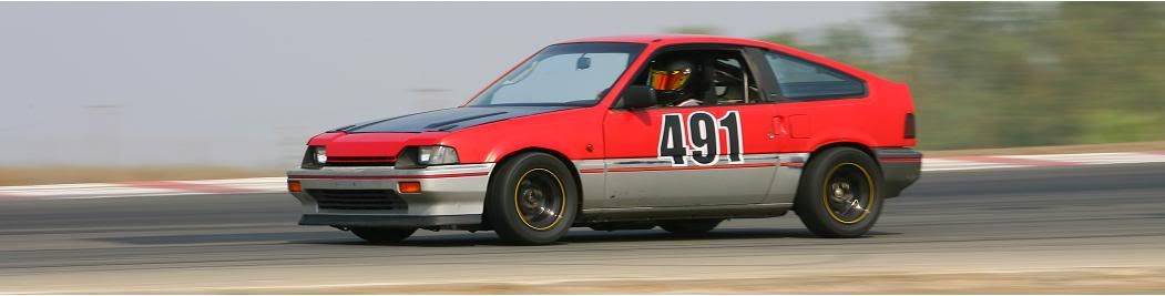
Triangulated Strut Tower Brace

After many hours of design, redesign, sketches, measuring, and remeasuring, I've finished my triangulated strut tower brace (stb). This design should provide more rigidity then the typical after market, over the engine, pinned-end curved beam stbs that are passed off as stiffening structure. dry.gif .

So, FWIW, here's what I did...

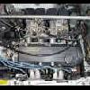
I first decided not to go over the engine, but, rather, to triangulate each strut tower bar to the middle of the firewall. I wanted to shear the stb axial load through the vertical firewall shear panel, and the windshield wiper trough's horizontal shear panel. In the wiper trough, I found a flat section in the middle of the panel between the stiffening beads. I wanted to tie the wiper trough shear panel to the firewall shear panel w/a steel angle to provide a better fore-aft shear load path.

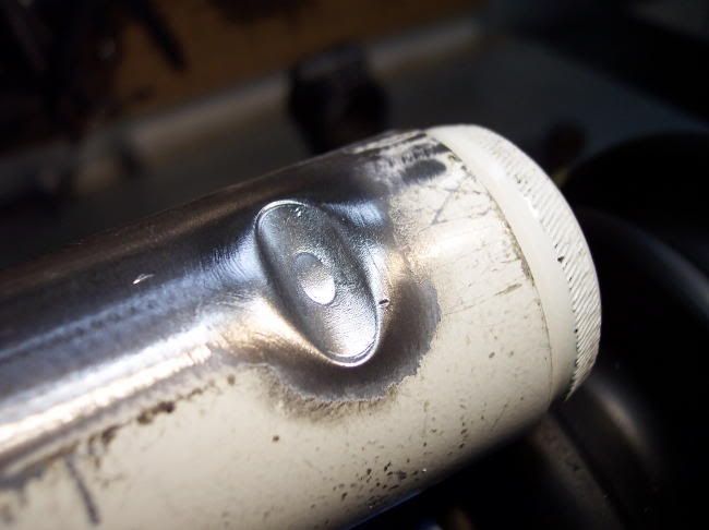
So, first I made room for this angle's vertical flange by "wacking" off an offending nut plate:


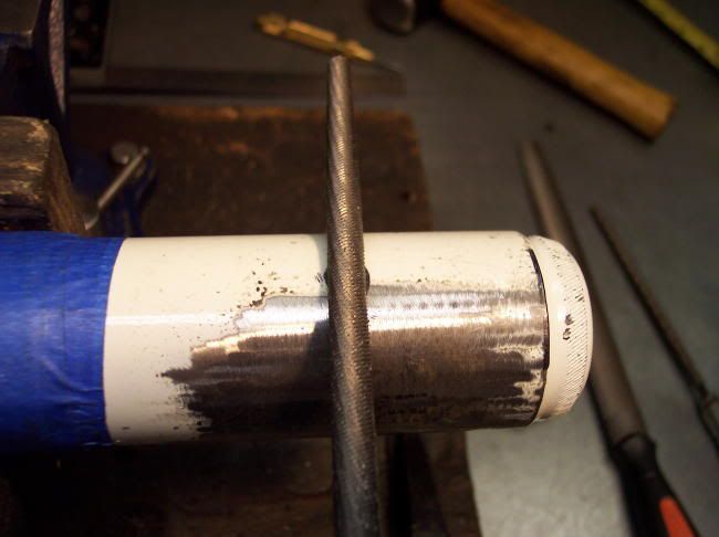
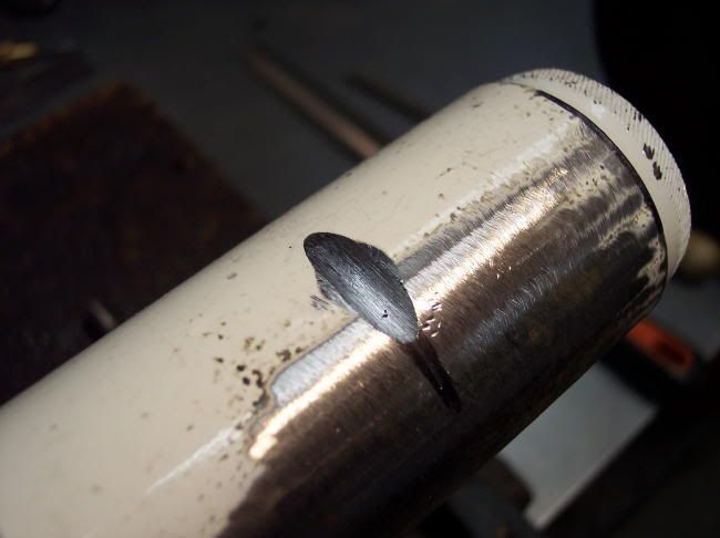
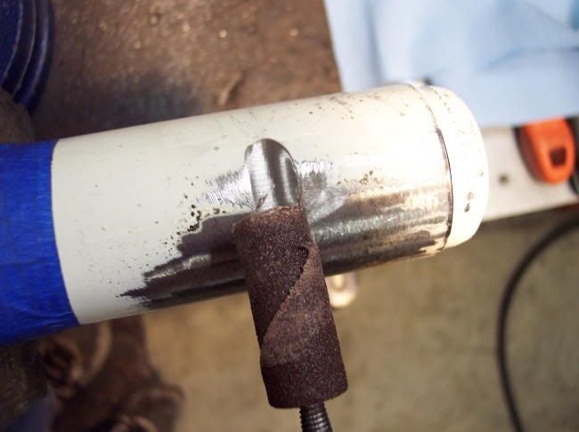
The vertical flange of my angle will bolt up here, so after chiseling off the nut plate, I ground the spot welds flat. I next employed my digital high speed metal band saw, which I nicknamed "Armstrong", and cut off a chunk of 2 x 3 x 3/16" steel angle:


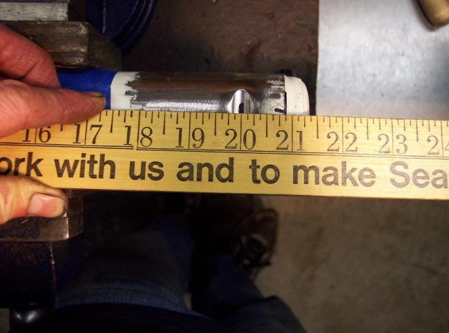
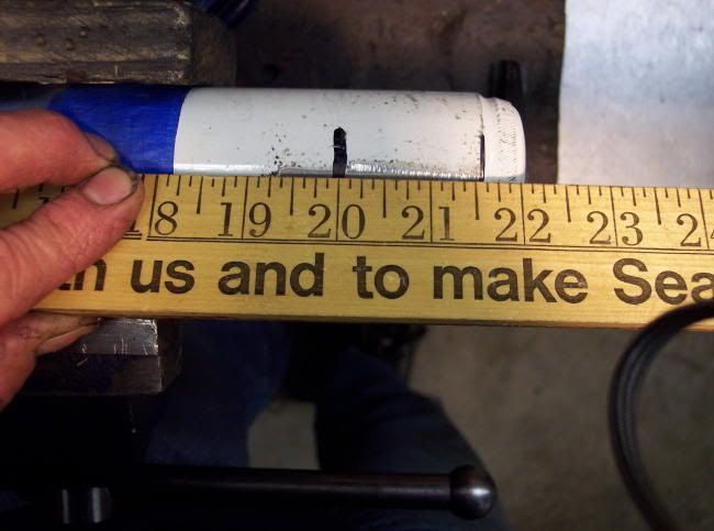
With a little more "whittling" and mock-up, I had a rough cut of the firewall/wiper trough angle. To connect the large angle to the wiper trough panel, I made some careful measurements and drilled the pilot holes for the bolt pattern on the angle. Using the pilot holes in the angle as a drill template, I drilled through the panel:


Since the nuts for the bolts that attach the angle to the wiper trough will be inside the car and I can't reach the bolt heads to prevent them from turning when installing, I welded the six Grade 8 bolts to the angle. After double checking the fit, I painted and installed the center brackets:


...from inside the car, under the "dash":


...and on the firewall side:


The firewall angle is attach on the flange where the vertical firewall panel is welded to the horizontal wiper trough panel. I chose to attach it here because the firewall is stiffer here where the two shear panels are joined...this locn provides a transverse shear path (firewall) and a fore-aft shear path (wiper trough). I used a 3/16" steel angle to provide bending stiffness for any overturning moment caused by the offset of the firewall angle attachment w/the wiper trough attachment. I believe this center connection provides sufficient stiffness.

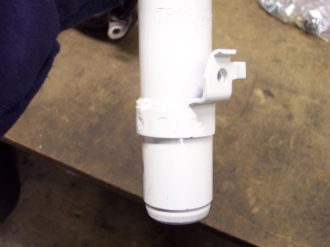
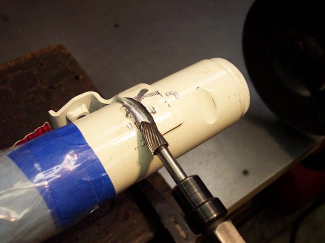
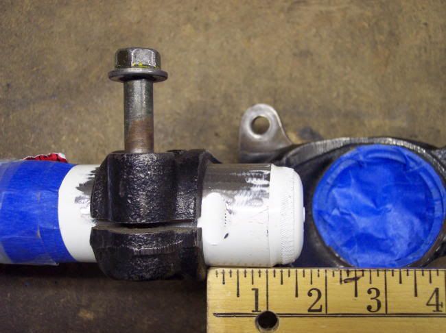
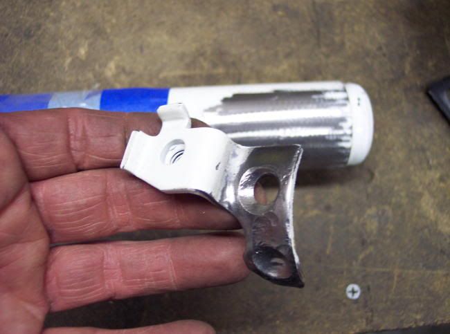
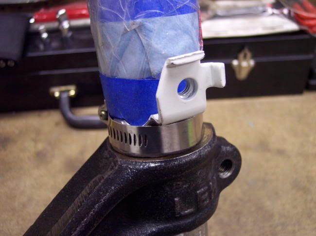
Next up was designing and fabbing the strut tower brackets themselves. I've decided to move ahead w/my project w/o the TEIN suspension kit. So, I designed a strut tower that incorperates the oem strut top...no camber adjustment. If and when the TEIN kit comes in, I'll change this design out for the much anticipated Mr.D adj camber plates.

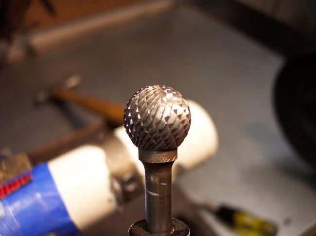
I came up w/a design where I did not have to cut an inside radius (to go around the strut top). Inside radius cuts in .125" steel plate are difficult w/o a plasma cutter (yes, the Kakagarage has no plasma cutter today) and I didn't feel like "daisy-chaining" drilled holes. So, I came up w/a design that uses nothing but 1/8" mild steel angles...


...that are cut & "machined" into specific shapes...


...continued...

#743
kakabox

  • Turd Polisher
  • PipPipPipPipPip
    • Group: 2012 Contributor
    • Location:Seattle, WA 98115
    • Drives: from point 'A' to point 'B' daily.
    • Image Gallery
    Garage View Garage
...Triangulated STB continued...

The shapes were then put in a "jig" and welded together...


...and BAM!...strut tower brackets:


...continued...

#744
kakabox

  • Turd Polisher
  • PipPipPipPipPip
    • Group: 2012 Contributor
    • Location:Seattle, WA 98115
    • Drives: from point 'A' to point 'B' daily.
    • Image Gallery
    Garage View Garage
...Triangulated STB continued...

After final test fitting, painting, measuring bar lengths, sourcing the bars, ordering and waiting for delivery, here is the finished product...you can also see the final design of the engine "torque strut" installed:


I have to give lxndr a big Thank You for finding the rods. They are swedged aluminum steering panhard and radius rods that are 3/4" dia, 6061-T6 aluminum, tapped for 3/8-24 rod ends; I bought them here: http://www.speedwaym...emNo=910-351-16 ...they are hollow and light and very inexpensive at ~$10 ea. The rod ends are close tolerance, 3 piece, medium duty rod ends. They have hard anodized 7075-T6 aerospace quality aluminum bodies...heat treated, 5210 precision ground ball, and Kevlar race. Self lubricating Teflon liners to seal out dirt an debris: http://www.speedwaym...itemNo=117-0806

With the bars finally installed I was able to check some previously questionable clearances:
1. The stb clears the fuel filter and pressure gauge...


2. The engine torque link clears the "boosterless" MC...


...and,
3. the engine torque link clears (barely) the fuel rail & regulator:


The cost to fab the triangulated stb and engine torque link was, $112 for the rods and rod ends (inclds $10.61 for shipping), ~$10 worth of steel, ~$10 worth of fasteners for a total of ~$132 and about 40 hrs of design and fab!

Cheers! cool.gif

#745
87MugenProCR-X

  • Just Drive...
  • PipPipPipPipPip
    • Group: 2010 Contributing Member
    • Location:San Diego, Ca
    • Drives: 84 Honda CRX, 94 Honda Civic 4dr, 95 Volvo 850 Turbo Wgn, 91 Mazda Miata
That is an awesome looking STB!!!!

Julian

#746
lxndr

  • All work and no play makes LXNDR a dull boy. All work and no...
  • PipPipPipPipPip
    • Group: Members
NICE!!!

#747
slavteren

  • pervertet 17" lover!
  • PipPipPipPipPip
    • Group: Contributing Member
    • Location:Denmark
    • Drives: 86 civic zc - 86 crx zc - 87 civic racecar
    • Image Gallery
i just have to say thanks, i have thought of duing somethin similar, only more "lowtech" laugh.gif but i was afraid of clearence problems.. i gues i have to get working now...
My beloved civic

My life

user posted image

the most important weapon- is the heart af the worrior.

#748
kakabox

  • Turd Polisher
  • PipPipPipPipPip
    • Group: 2012 Contributor
    • Location:Seattle, WA 98115
    • Drives: from point 'A' to point 'B' daily.
    • Image Gallery
    Garage View Garage
Strut Mod for More Suspension Travel

I've decided not to wait for the TEIN kit but move forward and get the car done. To that end, I bought a pair of Tokico Illumina 5-way adj front struts (I already have new Illumina rear shocks that I'll use w/Ground Control coil overs courtesy of lxndr... smile.gif 
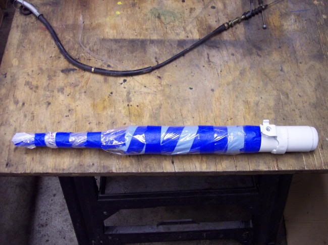
) I'm still on board to get the TEIN kit, but I can't wait any longer and want to get the car done. If and when the TEIN kit comes in, I'll swap out the Tokico's and either sell them off or save them for the next car... ph34r.gif.

So, here's the mod to allow for ~1/2" to ~3/4" more suspension travel w/oem length struts by allowing the struts to sit ~1/2" - 3/4" lower in the knuckle. The secret is removing the welded on brake line bracket...this thing:


I decided to grind off the welds...but, before I fired up the die grinder, I wrapped the polished strut rod and strut body w/protection to avoid getting grinding grit in the strut...look, Mr. Tokico is wearing a condom! blink.gif


Next step was to chuck it into my vice and fire up the compressor and using a die grinder, I ground off the inch long weld bead...


...I switched to a ball shaped rotary file...


...to grind out the two rosette welds holding on the bracket. Once the welds were ground down, the bracket offered no resistance to being pried off:


Clean up what's left of the welds...


The removal of the bracket allows the strut to sit lower in the knuckle. You can place the strut down in the knuckle as far as it will go w/o the axle's CV boot rubbing on the bottom of the strut body.


I don't have my new axles yet, so I don't know how far that will be...it should be somewhere around ~1/2" - 3/4". Also, a new groove for the strut clamp bolt has to be ground (filed) into the strut body once the lower position is determined. I'll use a round file, by hand, to make this groove.

If you don't completely destroy the brake line bracket upon removing, you can trim it and reuse it w/a hose clamp to secure the brake lines like it was intended for.


Cheers! cool.gif

#749
strudel

  • Leadfoot
  • PipPipPipPipPip
    • Group: 2011 Contributing Member
    • Location:Edmonton, AB
    • Drives: 2009 AUDI TT 3.2L, Project Teg powered Austin Mini Van
    • Image Gallery
QUOTE
Also, a new groove for the strut clamp bolt has to be ground (filed) into the strut body once the lower position is determined. I'll use a round file, by hand, to make this groove.

I've always wondered how this would turn out? How much can you grind away without puncturing the shock body? The same as the oem indent or less which would be enough for the bolt to pass? Sounds like it may be done in time for a first hand ride in May. JS

If you want one of these Logos send me a PM

aan.jpg


Austin Mini Van with DOHC Honda HP
http://www.angelfire.com/droid/strudel
Honda reliability and power combined with Mini cachet and style.


#750
kakabox

  • Turd Polisher
  • PipPipPipPipPip
    • Group: 2012 Contributor
    • Location:Seattle, WA 98115
    • Drives: from point 'A' to point 'B' daily.
    • Image Gallery
    Garage View Garage
Strut Mod for More Suspension Travel; Part II

Today I looked closer at the construction of the Tokico Illumina strut and discovered something interesting. The Illumina's are a "double tube" construction. In other words the strut tube has a damping cylinder inside. Look closely at this pic of the OE pinch bolt notch w/the paint removed and you can see what I mean:


You can see the outer wall of the inner damper through the hole created by the notch for the pinch bolt. I believe Tokico machines a cylinder w/an OD to fit the Honda knuckle. The inner bore of this cylinder is machined to fit their damping insert. The pinch bolt notch is machined before the two are assembled. The notch is machine clear through the strut tube's thickness, that's why you can see the inner damper insert peaking through the pinch bolt notch. The damping insert is probably swedged into the outer cylinder and the ends welded shut.

What this means is that you can machine another notch through the outer tube and you will not have a compromised, i.e., leaky, weakened strut...as long as you do not grind through the wall of the insert! I measured the depth of the OE machined pinch bolt notch and found it to be .100" deep...this makes sense as the outer cylinder's wall thickness appears to be .10".

Anyway, now that I knew I could machine another notch at least .10" deep w/o problems, I set about figuring out how much I could sink the strut in the knuckle w/o contacting the CV boot. I mounted an old 'teg axle in my vice and mocked up the strut/knuckle combo to check clearances at various depths. I found a 3/4" drop still had clearance between the boot and axle even at an extreme stub axle angle:


The oem notch locn is 7/8" from the edge of the knuckle housing:


I added 3/4" to this measurement and marked the new pinch bolt notch locn on the opposite side of the strut:


Using a rat-tail file, I filed a notch at this new locn:


As I filed, I kept checking to see I hadn't broken through the outer strut cylinder, and also, I kept checking to see if the pinch bolt would clear the strut...I wanted to remove just enough material for the bolt to be able to be threaded. When I had filed away enough material, I broke out the die-grinder and chucked up a sanding roll to smooth out my file marks:


...continued...